A Differential Pair Interface Based on Circulator
A differential pair and line interface technology, which is applied in the direction of waveguide devices, circuits, electrical components, etc., can solve the problems of unsuitable miniaturization and high integration, high production and development costs, large circuit area, etc., and achieve compact structure, The form is simple, ensuring the effect of the overall structure
- Summary
- Abstract
- Description
- Claims
- Application Information
AI Technical Summary
Problems solved by technology
Method used
Image
Examples
Embodiment Construction
[0029] For ease of understanding, the specific implementation structure and workflow of the present invention are described below in conjunction with the accompanying drawings:
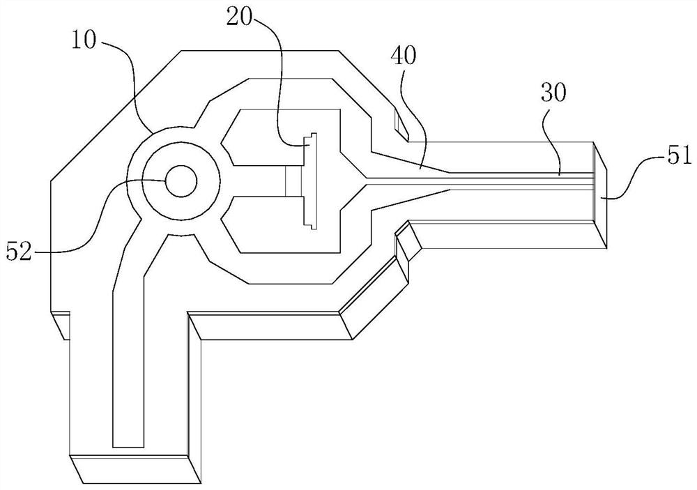
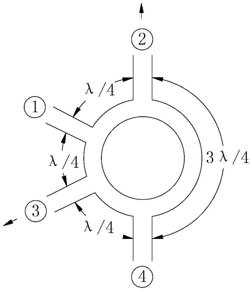
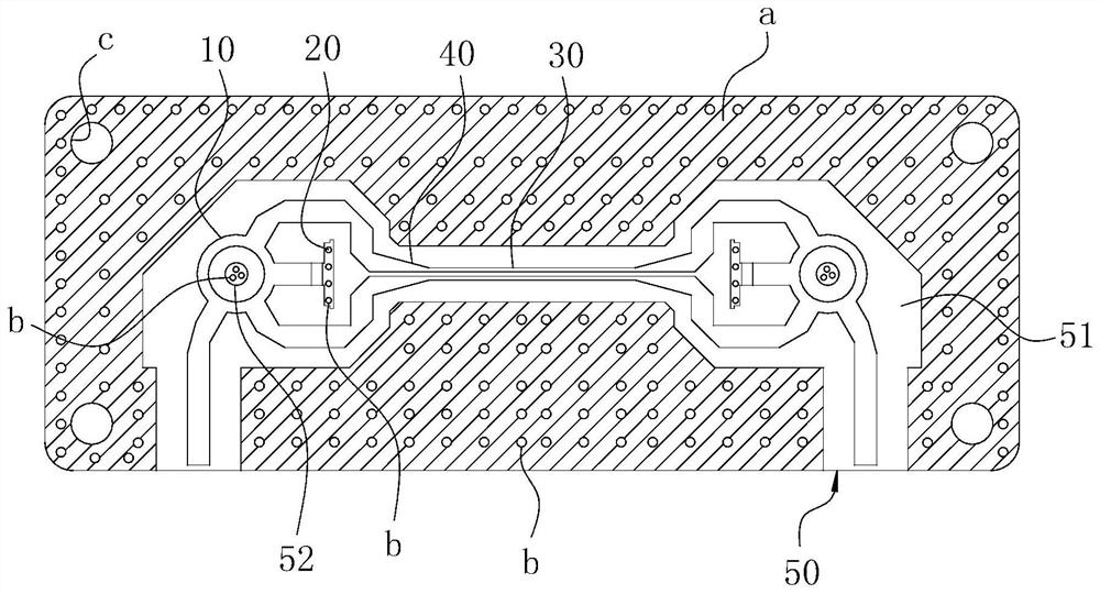
[0030] Concrete structure of the present invention, as Figure 1-2 As shown, it includes a dielectric plate 50 as a carrier. One side of the dielectric board 50 is covered with copper, while the other side is provided with a cavity structure; the cavity structure is covered with a structure such as figure 1 The planar microstrip plate a. The main structure of the planar microstrip board a includes a microstrip hybrid ring 10 , a 50Ω surface mount resistor 20 , a matching balun 40 and a differential pair 30 . Among them: refer to figure 2 As shown, the radio frequency signal is input by the microstrip hybrid ring 10, that is figure 2 The port ④ in the input is turned into an equal-amplitude anti-phase signal, and then the two output terminals are figure 2 The middle port ② and port ③ are finall...
PUM
 Abstract
Description
Claims
Application Information
 - R&D
- Intellectual Property
- Life Sciences
- Materials
- Tech Scout
- Unparalleled Data Quality
- Higher Quality Content
- 60% Fewer Hallucinations
Browse by: Latest US Patents, China's latest patents, Technical Efficacy Thesaurus, Application Domain, Technology Topic, Popular Technical Reports.
© 2025 PatSnap. All rights reserved.Legal|Privacy policy|Modern Slavery Act Transparency Statement|Sitemap|About US| Contact US: help@patsnap.com


