
Suspended substrate low loss coupler

a coupler and substrate technology, applied in the direction of multiple-port network, electrical apparatus, waveguides, etc., can solve the problems of low-loss and high-power handling, difficult to achieve tight spacing requirements in low-cost printed circuit processes, and direct addition of coupler insertion loss to the overall noise figure of the receiver module. , to achieve the effect of improving isolation, reducing vswr, and low cos

Active Publication Date: 2005-05-19
NORTHROP GRUMMAN SYST CORP
View PDF4 Cites 3 Cited by
  • Summary
  • Abstract
  • Description
  • Claims
  • Application Information

AI Technical Summary

Benefits of technology

[0007] The present invention addresses the foregoing need through provision of a low loss suspended substrate coupler which includes a dielectric substrate, a first conductor metallization forming a first transmission line on a topside of the substrate and a second conductor metallization forming a second transmission line on the bottom side of the substrate. To provide closer mode velocity matching, a key feature of the coupler is the provision of capacitive loading or coupling to ground at discrete intervals between the transmission line on the topside of the substrate and the transmission line on the bottom side of the substrate. This capacitive loading is formed by incorporating capacitance stubs in each transmission line section at pre-selected intervals, each of which is opposite a corresponding one of a plurality of grounded stubs on the other side of the substrate. This capacitive loading to ground at discrete intervals along the transmission line represents a low cost method for providing closer even to odd mode velocity matching across a given frequency bandwidth, corresponding to improved isolation and lower VSWR.
[0008] Preferably, to improve performance, the coupler design also uses substrate vias to provide microstrip interfaces and microstrip matching elements on one side of the substrate for the coupler ports at both ends of each coupled transmission line. In addition, the substrate coupler is preferably mounted in an enclosure with controlled spacing to ground above and below the substrate to control the transmission line impedance of the coupled lines and to provide shielding of the coupler.

Problems solved by technology

Any coupler insertion loss will directly add to the overall noise figure of the receiver module.
For transmitter modules, low-loss and high power handling is critical if the coupler follows the power amplifier.
These tight spacing requirements are difficult to achieve in low cost printed circuit processes.
Lange couplers are also not suited for low cost printed circuit implementation because of the need for crossovers to interconnect the alternate fingers.
Waveguide couplers can handle high power RF signals with low loss but are very large at cell phone frequencies and are not suitable for integration with active devices.
Suspended stripline couplers can be fabricated as a single layer printed circuit board but normally have the disadvantage of very different even and odd mode velocity in coupled transmission line structures.
The difference in coupled line phase velocity causes generally poor performance for simple suspended stripline couplers.

Method used


Image

  • Suspended substrate low loss coupler
  • Suspended substrate low loss coupler
  • Suspended substrate low loss coupler

Examples


Embodiment Construction

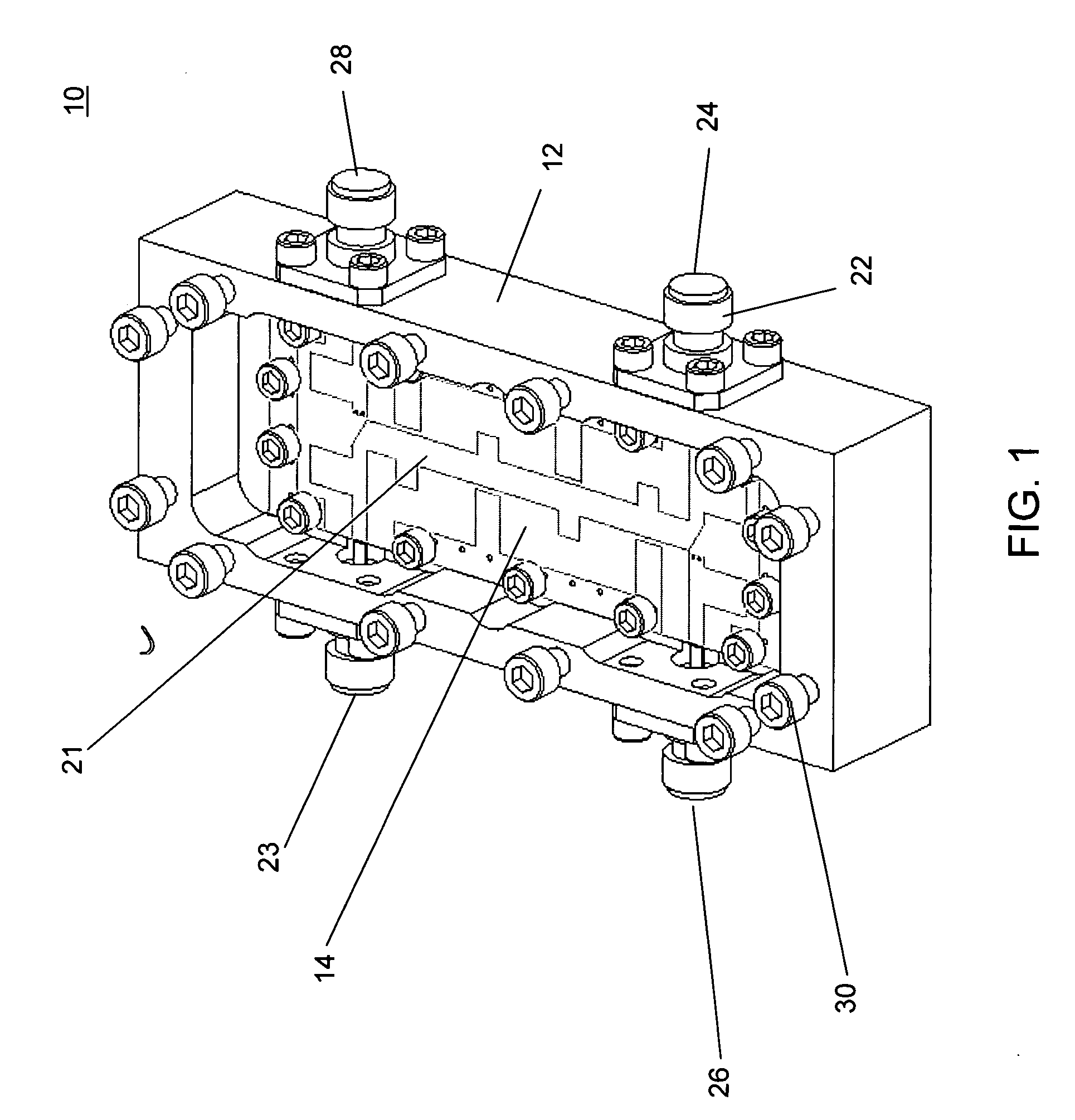
[0014]FIG. 1 illustrates a suspended substrate quadrature coupler 10 that is constructed in accordance with the preferred embodiment of the invention. The coupler 10 includes a housing 12, which is preferably made form metal, metal coated plastic or any other suitable electrically conductive material and includes a removable cover 13. Disposed in the housing 12 is a dielectric substrate 14.

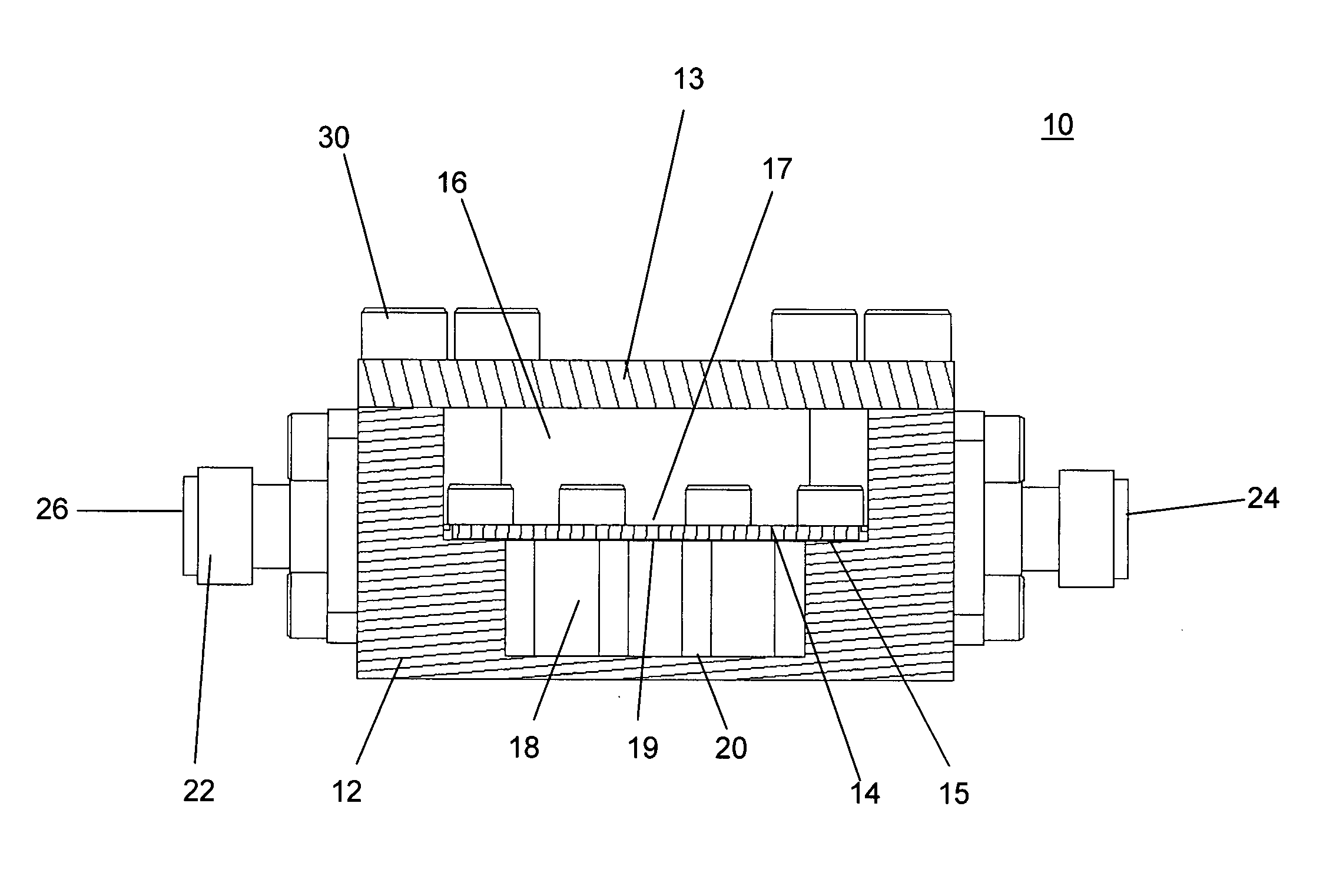
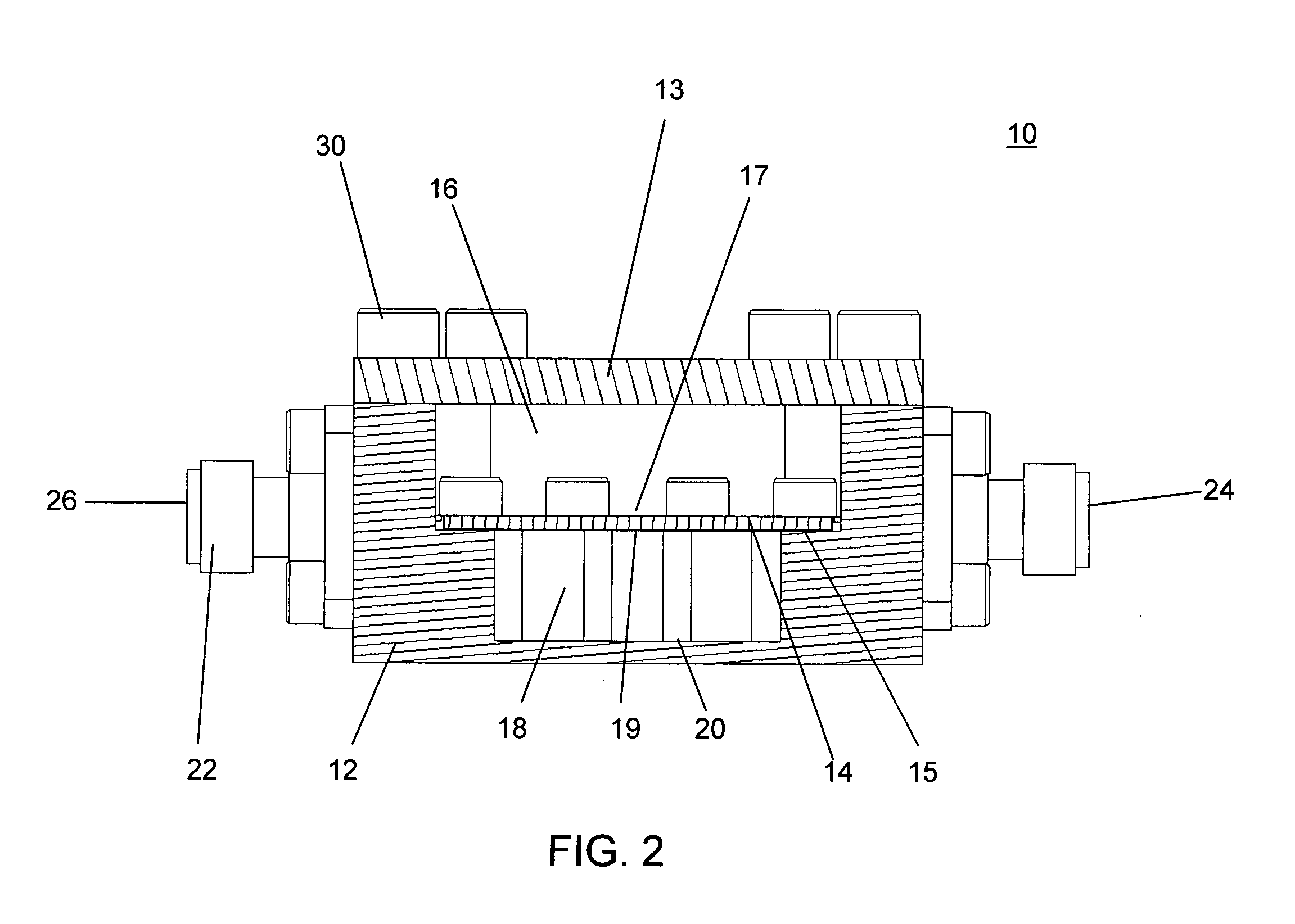
[0015] As illustrated in FIG. 2, the substrate 14 is mounted on a ledge 15 of the housing 12 in a suspended manner such that a first cavity 16 is formed between a topside 17 of the substrate 14 and the cover 13, while a second cavity 18 is formed between a bottom side 19 of the substrate 14 and a floor 20 of the housing 12. A transmission line coupler circuit 21 is formed on both the top and bottom sides of the substrate 14 as will be discussed in detail in conjunction with FIGS. 3A and 3B. The mounting of the substrate 14 in the housing 12 with controlled spacing to ground above and below the su...


PUM


Abstract

A low loss suspended substrate coupler includes a substrate having a first transmission line disposed on a topside of the substrate and a second transmission line disposed on the bottom side of the substrate, thereby providing broadside transmission line coupling. To provide closer mode velocity matching, the coupler has capacitive loading or coupling to ground at discrete intervals between the two transmission lines. The capacitive loading is formed by integrating stubs in each transmission line at pre-determined intervals, each of which is opposite a corresponding one of a plurality of ground stubs on the other side of the substrate. The ground stubs are connected to ground at the outer edge of the coupler area with substrate vias or directly to the coupler housing.

Description

BACKGROUND OF THE INVENTION [0001] 1. Field of the Invention [0002] The present invention relates in general to a suspended substrate quadrature coupler for combining two receive or transmit amplifiers for increased power output, reduced port VSWR and improved reliability. [0003] 2. Description of the Background Art [0004] There is a need for low cost, low insertion loss, high-power handling capability quadrature couplers that can be inserted into an integrated circuit module assembly (IMA). For receiver modules, insertion loss is critical to minimize the noise figure contribution between the antenna and the first low noise amplifier. Any coupler insertion loss will directly add to the overall noise figure of the receiver module. For transmitter modules, low-loss and high power handling is critical if the coupler follows the power amplifier. For transmit applications, the coupler may need to handle over one hundred watts of RF output signal from two power amplifiers. The coupler nee...

Claims


Application Information

Patent Timeline
Patent Type & Authority Applications(United States)
IPC IPC(8): H01P5/18
CPCH01P5/187
Inventor ALLEN, BARRY ROSSKO, DANIEL KWOK-HUNGBRUNONE, DAVID JOSEPH
Owner NORTHROP GRUMMAN SYST CORP
Learn More