
Precision release eye dropper bottle

Inactive Publication Date: 2003-10-14
ACU I DROP
View PDF14 Cites 41 Cited by
  • Summary
  • Abstract
  • Description
  • Claims
  • Application Information

AI Technical Summary

Benefits of technology

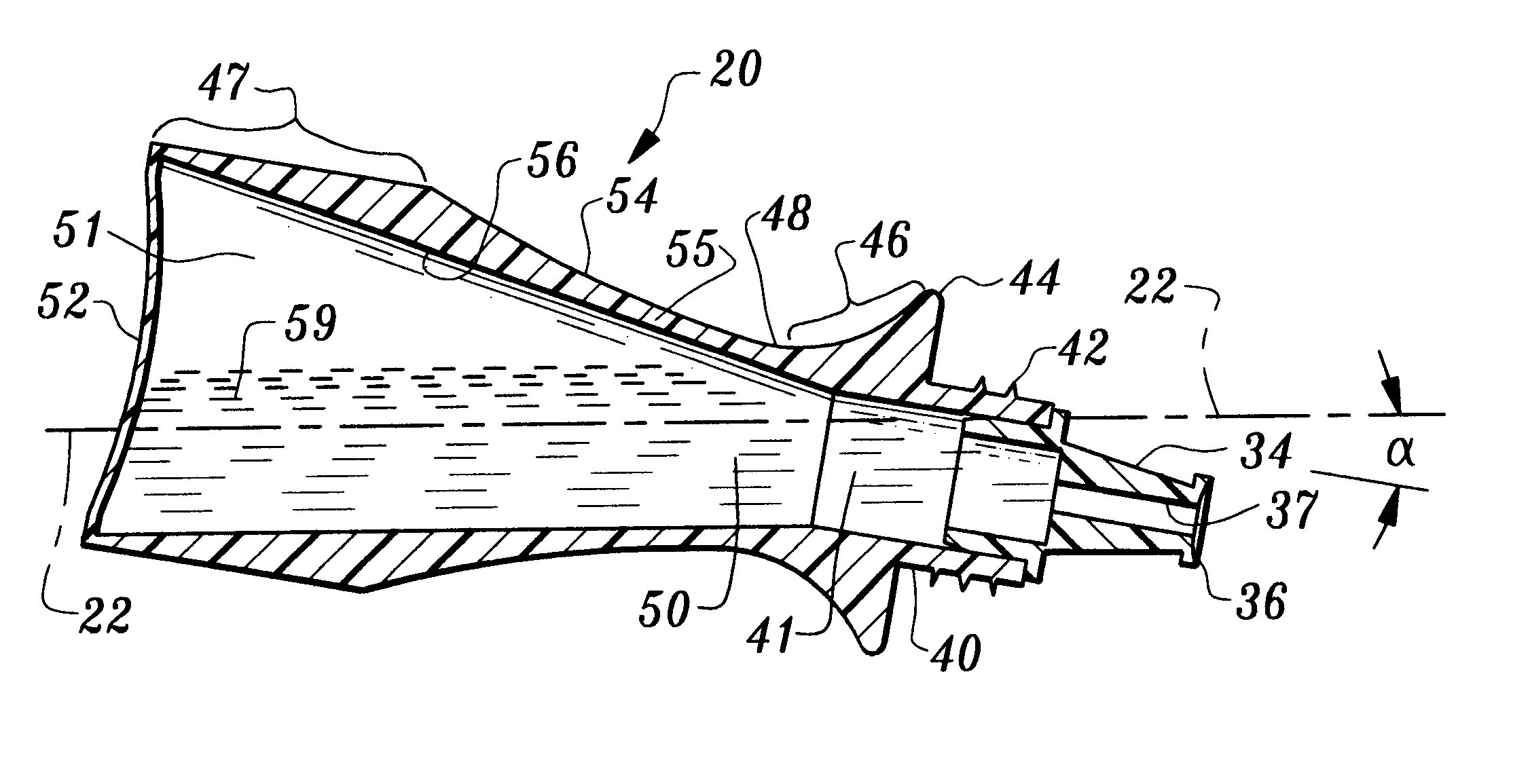
A primary object of the present invention is to provide an eye liquid dispensing bottle that allows virtually all the liquid in the bottle to be discharged therefrom in the form of drops while held in a near horizontal orientation.
Another object of the present invention is to provide a bottle configured to give an accurate and consistent alignment between the tip of the dropper and an eye for precise drop instillation.
Another object of the present invention is to provide an eye dropper bottle which maximizes utilization of the medicinal liquid within the reservoir, thereby avoiding waste.
Another object of the present invention is to provide a bottle which minimizes the number of drops which might fall on the skin of the face rather than in an eye.
Another object of the present invention is to provide an eye bottle configured to be supported against the bridge of the nose for both alignment and ease of eye drop instillation.
Another object of the present invention is to provide a bottle whereby a caregiver, by holding the bottle in a near horizontal orientation below the line of vision and to the side, can more easily instill drops inside the eyelid of an individual unable to do so for himself / herself.

Problems solved by technology

The instillation of medicinal eye drops tends to be difficult and annoying for many individuals.
Often, however, the drop misses the eye altogether and falls on the face, where it has no therapeutic value and may even be irritating to the skin.
Or, several drops might be released if there is a momentary delay in the first drop and a second one is squeezed from the bottle, causing an overdose and waste of medicine.
There are several factors that often complicate the conventional way of instilling eye drops.
First, it is difficult for some individuals, especially the elderly, to elevate their shoulder high enough to place the eye dropper in an ideal position above the eye.
Secondly, limitation of motion of the hand or the wrist makes it difficult to turn the bottle in a substantially inverted position.
Thirdly, some individuals, as they grow older, find that their hands and head are no longer steady, thus posing the problem of not being able to maintain proper alignment while the drops are being instilled.
Yet, in spite of all the advances in the medications themselves, little or no progress over the past 40 years or more has been made in the way the drops are delivered to the patient.
Often the caregiver finds it difficult to get the patient to open their eyes widely while the drops are being instilled.
This makes it difficult to instill the drops with any accuracy and often the drop misses the eye and runs down the cheek.
However, the bulkiness of these devices, problems with maintaining sterility, and the tremendous variation in bottle sizes, all keep these devices from being widely used.
Again, it has not solved the delivery system problems that exist.
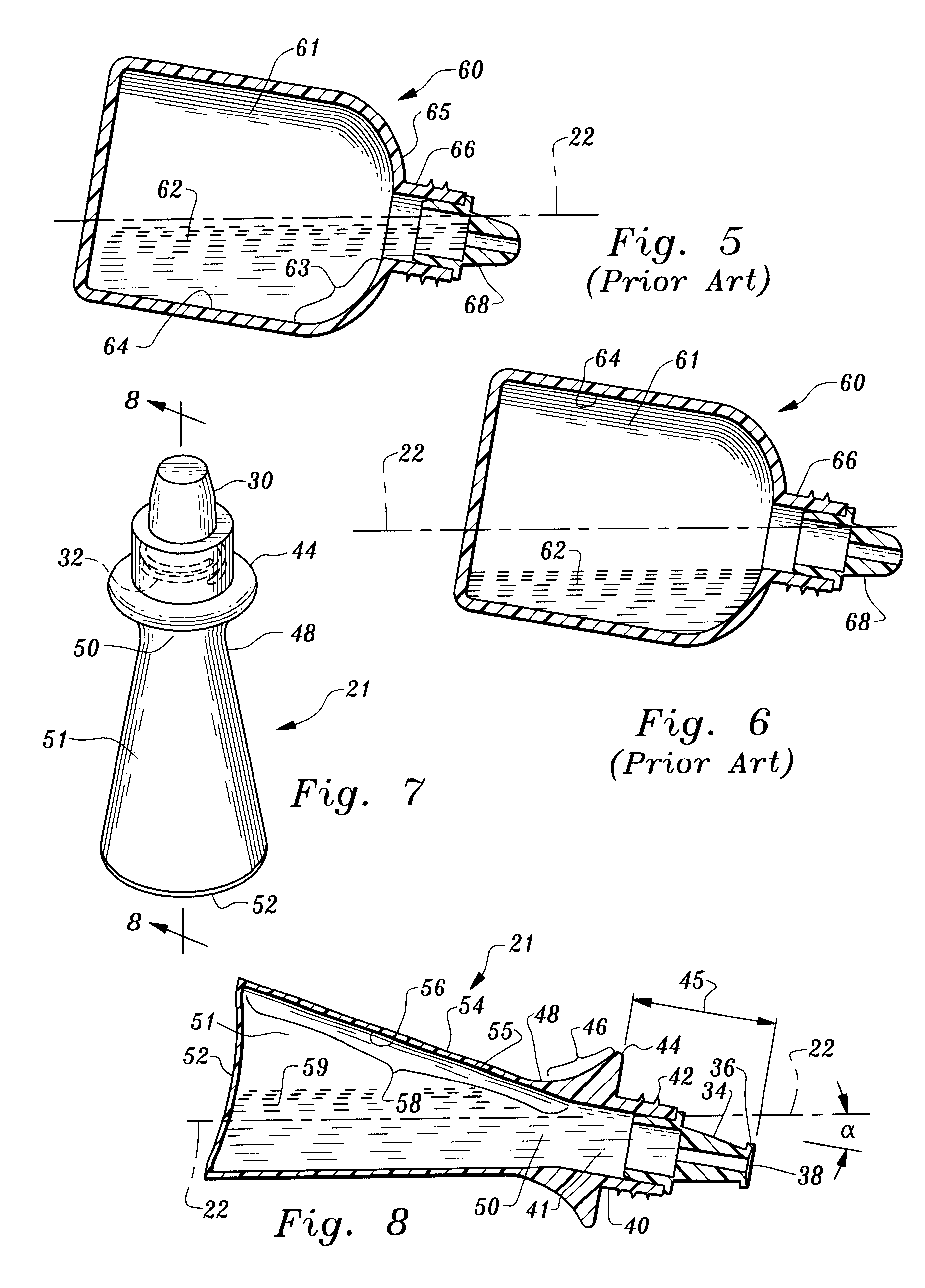
However, with today's standard eye bottles, a large portion of the liquid remains in the reservoir when the bottle is held in a horizontal position.
When this occurs the drop usually misses the target altogether.
When the proper positioning has been achieved, the user compresses the walls of the bottle with the fingers, causing a drop to fall into the eye.
Usually, if done quickly and properly, the patient will hardly know the drop was instilled.

Method used


Image

  • Precision release eye dropper bottle
  • Precision release eye dropper bottle
  • Precision release eye dropper bottle

Examples


Embodiment Construction

, the drawings, and the claims.

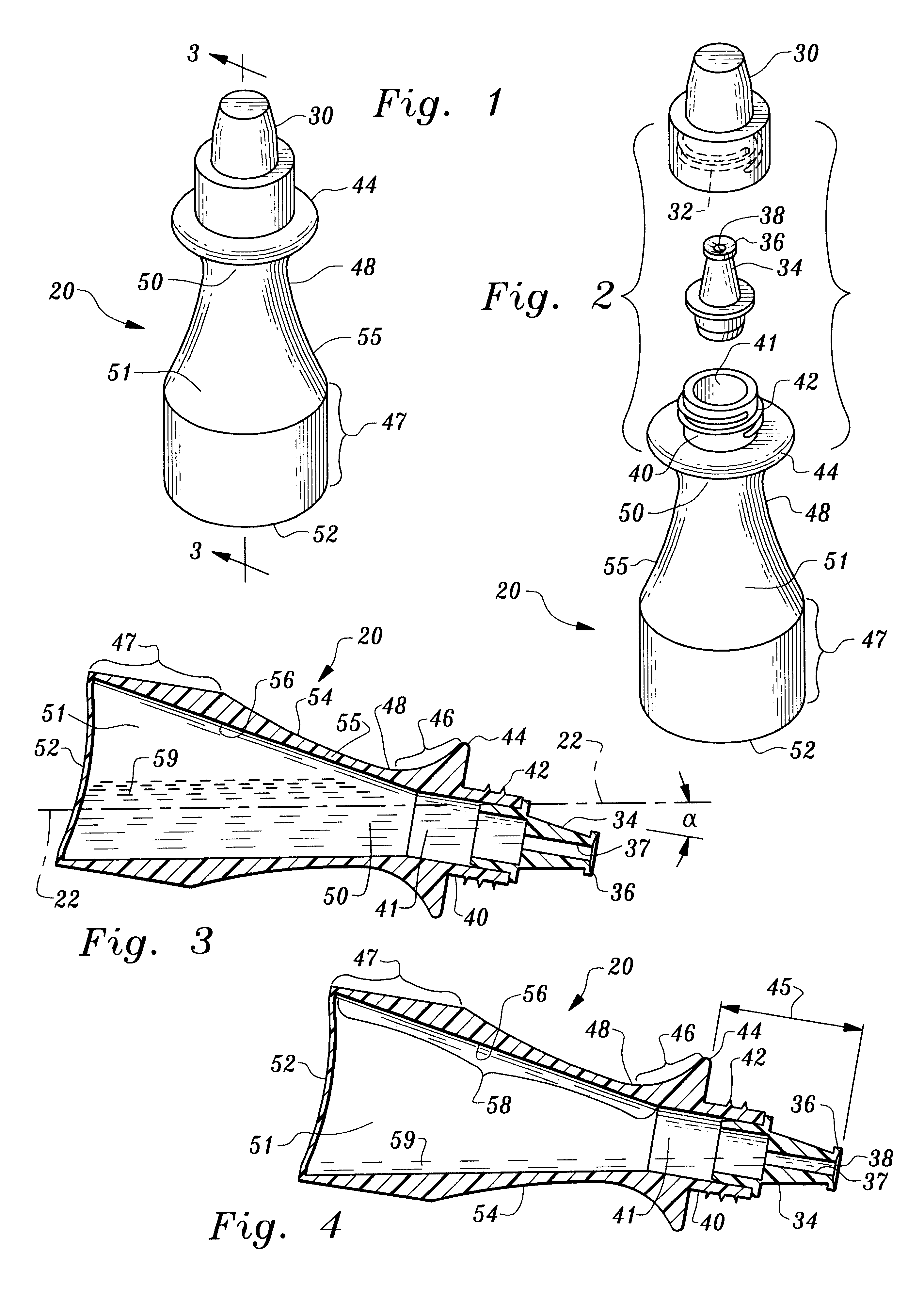
FIG. 1 is a perspective view of an assembled most preferred embodiment of the present invention.

FIG. 2 is an exploded perspective view of the most preferred embodiment of the present invention.

FIG. 3 is a sectional view 3--3 of FIG. 1 of the most preferred embodiment of the present invention with a large amount of liquid present in the reservoir.

FIG. 4 is a sectional view 3--3 of FIG. 1 of the most preferred embodiment of the present invention with minimal liquid present in the reservoir.

FIG. 5 is a sectional view of a prior art bottle in a near horizontal orientation with a large amount of fluid present in the reservoir.

FIG. 6 is a sectional view of a prior art bottle in a near horizontal orientation with a smaller amount of fluid present in the reservoir.

FIG. 7 is a perspective view of an assembled preferred embodiment of the present invention.

FIG. 8 is a sectional view 8--8 of FIG. 7 of a preferred embodiment of the present invention with a reservoi...


PUM


Abstract

An eye dropper bottle <HIL><PDAT>20 < / BOLD><PDAT>is provided which allows a person to instill drops D into an eye E while the bottle <HIL><PDAT>20 < / BOLD><PDAT>is held in a near horizontal orientation <HIL><PDAT>22< / BOLD><PDAT>. The bottle <HIL><PDAT>20 < / BOLD><PDAT>has a reservoir <HIL><PDAT>51 < / BOLD><PDAT>for holding a liquid <HIL><PDAT>59< / BOLD><PDAT>. The reservoir <HIL><PDAT>51 < / BOLD><PDAT>includes a base <HIL><PDAT>52< / BOLD><PDAT>, an upper end <HIL><PDAT>50< / BOLD><PDAT>, and compressible walls <HIL><PDAT>55< / BOLD><PDAT>. The bottle <HIL><PDAT>20 < / BOLD><PDAT>further includes a neck <HIL><PDAT>40 < / BOLD><PDAT>into which a dropper tip <HIL><PDAT>34 < / BOLD><PDAT>fits. The neck <HIL><PDAT>40 < / BOLD><PDAT>has external threads <HIL><PDAT>42 < / BOLD><PDAT>onto which an internally threaded <HIL><PDAT>32 < / BOLD><PDAT>cap <HIL><PDAT>30 < / BOLD><PDAT>fits. The internal surface <HIL><PDAT>56 < / BOLD><PDAT>of the walls <HIL><PDAT>55 < / BOLD><PDAT>of the reservoir <HIL><PDAT>51 < / BOLD><PDAT>maintains a constant slope <HIL><PDAT>58 < / BOLD><PDAT>of a predetermined angle to allow virtually all the liquid <HIL><PDAT>59 < / BOLD><PDAT>of the reservoir <HIL><PDAT>51 < / BOLD><PDAT>to flow toward a dropper tip <HIL><PDAT>34 < / BOLD><PDAT>where it can be discharged in the form of drops D while the bottle is held in a near horizontal orientation <HIL><PDAT>22. < / BOLD>< / PTEXT>The bottle <HIL><PDAT>20 < / BOLD><PDAT>is grasped with a thumb T parallel to the length of the bottle <HIL><PDAT>20 < / BOLD><PDAT>and an index finger F wrapped around a sulcus <HIL><PDAT>48< / BOLD><PDAT>. The bottle is held in a near horizontal orientation over an eye E with the nail N of the thumb T resting against the upper bridge B of the nose. A predetermined distance <HIL><PDAT>45 < / BOLD><PDAT>between a flange <HIL><PDAT>44 < / BOLD><PDAT>and the distal end <HIL><PDAT>36 < / BOLD><PDAT>of the dropper tip <HIL><PDAT>34 < / BOLD><PDAT>causes the drop D to consistently and accurately align with an eye E.< / PTEXT>Drops D may also be instilled by holding the bottle <HIL><PDAT>20 < / BOLD><PDAT>above and over an eye E in a near horizontal orientation <HIL><PDAT>22. < / BOLD>< / PTEXT>

Description

This invention relates to eye dropper bottles for dispensing liquids. More particularly, this invention relates to bottles for instilling medicinal liquids into a person's eye while the head is tilted back and the bottle is held against the bridge of the nose in a near horizontal orientation. This invention also is used for instilling drops into an eye by tilting the head back and holding the bottle in a near horizontal orientation with the dropper tip above and over an eye.The instillation of medicinal eye drops tends to be difficult and annoying for many individuals. Generally, a person tilts their head back and looks up. Simultaneously, the dropper bottle is elevated above the eye and held in an inverted position while the walls are squeezed, causing the drop to fall toward the eye. If the lower eyelid is retracted down at the same time, the drop will more easily find its target.Often, however, the drop misses the eye altogether and falls on the face, where it has no therapeutic ...

Claims


Application Information

Patent Timeline
IPC IPC(8): A61F9/00
CPCA61F9/0008
Inventor HAGELE, JAMES
Owner ACU I DROP
Learn More