
Range finder

a range finder and range technology, applied in the field of range finders, can solve the problems of difficult to position the user or himself from a target, the useful device is more complicated for short-range distance determination, and the effectiveness of image-based range finders to date is quite limited, so as to achieve the effect of easy positioning the user or herself from a targ

Inactive Publication Date: 2003-10-21
FAULKNER ROBERT L
View PDF6 Cites 34 Cited by
  • Summary
  • Abstract
  • Description
  • Claims
  • Application Information

AI Technical Summary

Benefits of technology

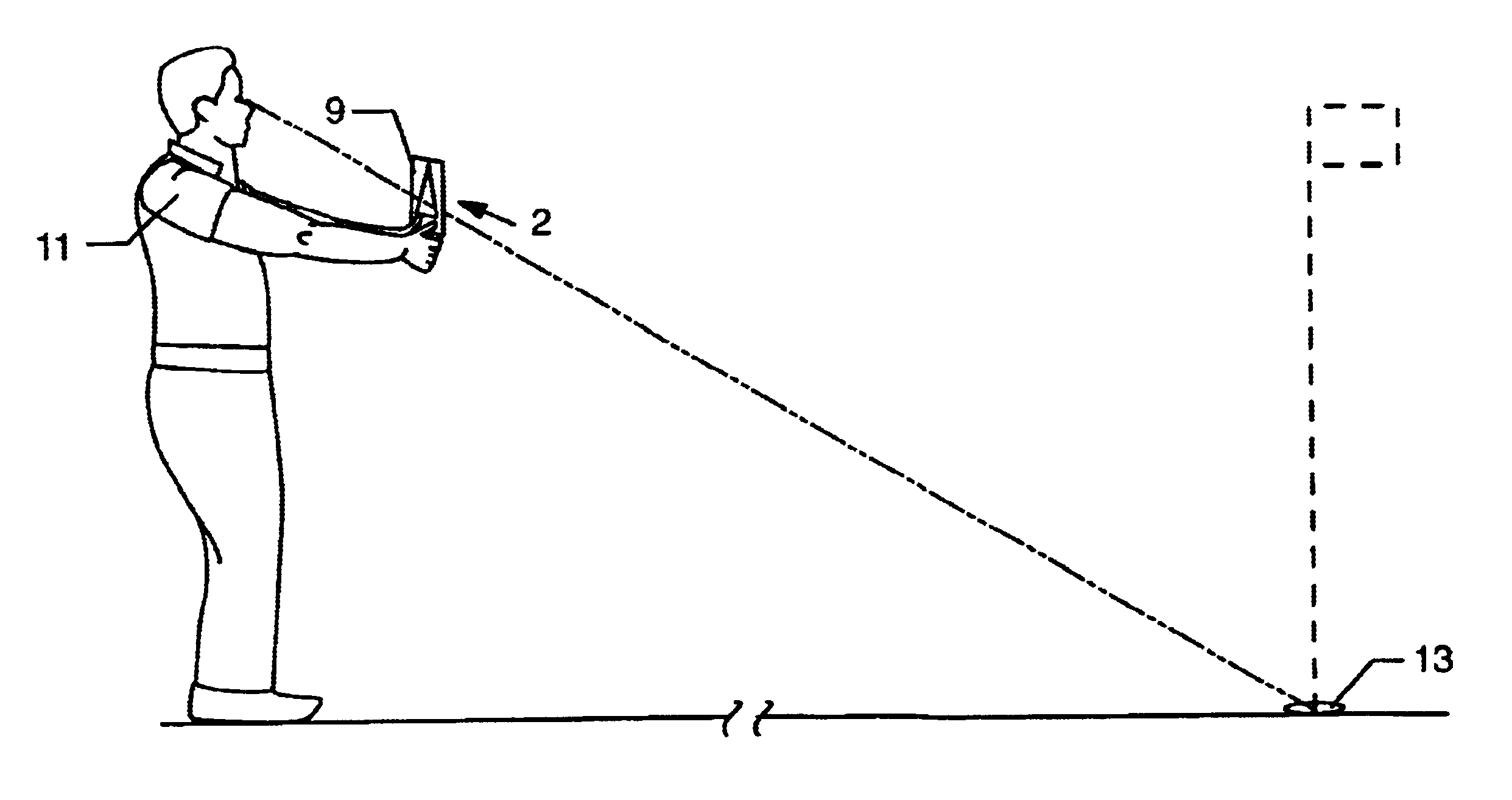
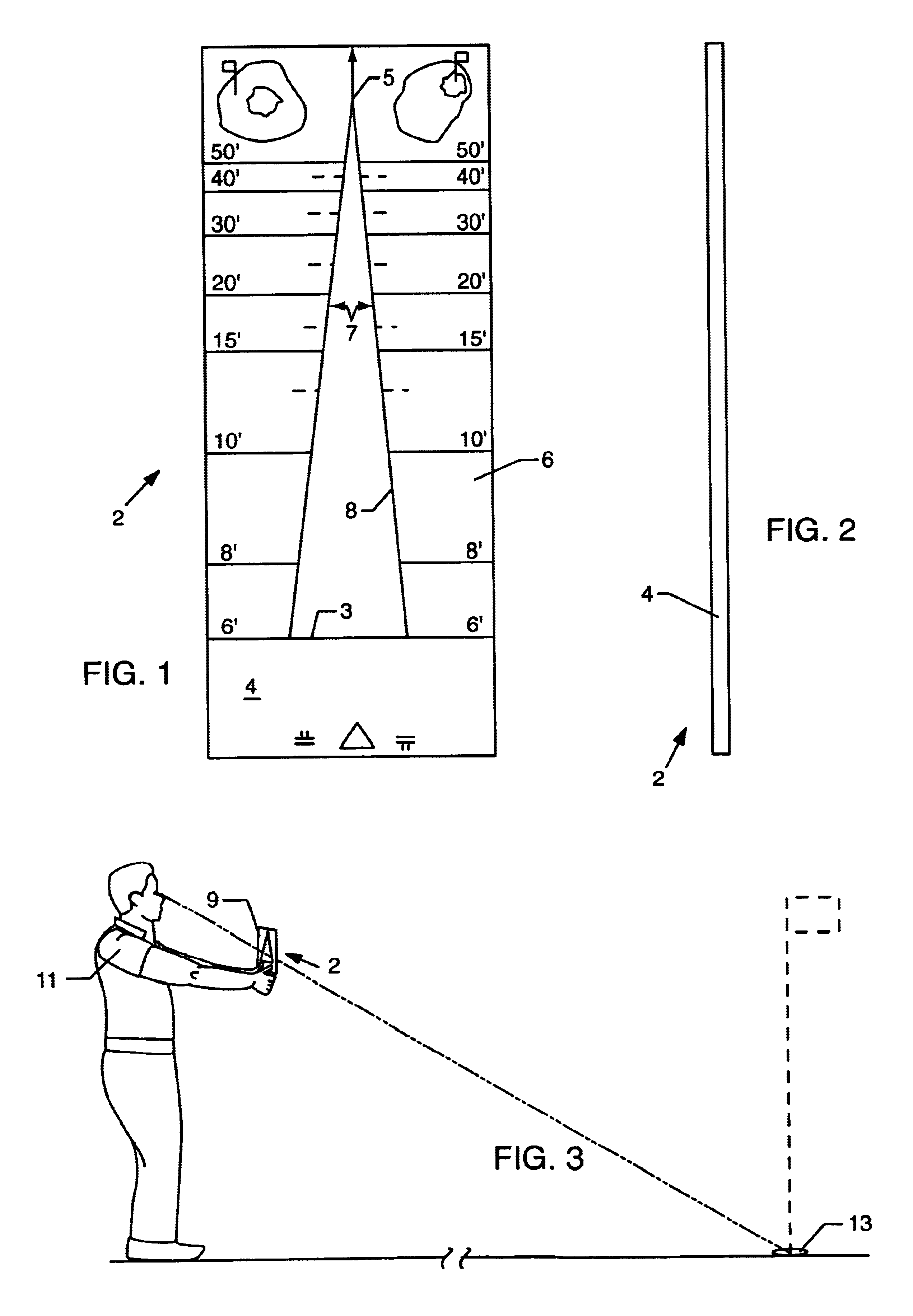
The instant invention is an image-based range finder. In each of its embodiments, the invention relates to, and relies on, the fact that the image of an object appears to decrease in size as distance from the object increases. The invention expands dramatically the types of image-based range finders that may be constructed by eliminating the need to depend on curvilinear shapes on equally spaced lines and markings. The invention further incorporates a new use of image-based range finders by determining relatively short ranges to relatively small objects, and determining distances from an object on the ground to another object on the ground at the user's feet or to the user.
When the invention is to be used to estimate relatively close distances from an object on the ground at the user's feet, such a golf ball, or the user himself, and another object on the ground, such as the golf hole, an additional adjustment to the opening or distance information is needed to account for the height of the user, or a chosen average height. The z=xy / d formula as described above is adjusted in accordance with the additional formula a.sup.2 =b.sup.2 +c.sup.2 (where a is the distance from the eye to the desired object, b is the height of the eye, and c is the distance from the object at the user's feet or the user's feet to the desired object) to provide for the correct eye to desired object distance. While this formula could be theoretically considered in all distance determination instances, its practical relevance increases in circumstances such as these. Through use of this additional formula, the distance information and distance markings can be accurately determined. In some cases, the device can be implemented with averaged data. In such circumstances, the more accurate information provided based upon the application of the additional formula above would allow for more accurate average information for inclusion in the device as well. In some circumstances, additional trial and error observations may prove useful to take into account other variables such as the method of holding the device or vision adjustments at very close distances.
(1) is relatively simple, light-weight, portable, low-cost, and rugged, particularly as compared to signal reflection range finders;
(11) can be made to allow a target shooter, archer or other person to more easily position him or herself from a target;
(12) can be made to provide a hunter, soldier or any other person with a distance determination problem with a range finder that can replace, complement, back up or test existing signal reflection range finders;

Problems solved by technology

Image-based range finders have to date been quite limited in their effective uses.
This is not surprising because making a useful device is more complicated for short-range distance determination.
Although such adjustments are not always necessary, they would likely have presented significant difficulties.
In addition, we understand that image-based range finders have thus far not been used to estimate distances to relatively small objects (i.e., objects with a linear dimension of less than 1.5 feet), such as a golf hole on the golf green.
Useful applications for such a device would have been thought limited given that (1) absent a magnifying element, only short ranges can be determined, and (2) the less distance involved, the more likely the need for precision.
In these conditions, the prior art, thought applicable in theory, may well have been an impractical option because (1) a user of a reference-line device would have great difficulty pin-pointing image size with sufficient, precision to yield a reasonably precise result; and (2) the maker of a stadia-line or window-based device, as discussed more fully, below, would need to form either a very long opening to accommodate the window or lines or make the distance-indicating lines very close together.
Thus assuming anyone had thought to apply the prior art to short-range applications, it would not have been obvious that a practically useful device could be made.
Further, image-based range finders have not been used to determine distances from the user or an object on the ground at the user's feet, such as a golf ball, to another nearby object on the ground, such as a golf hole.
The application of the z=xy / d formula alone will not render an accurate result in this context.
Thus, any device based solely on the z=xy / d formula could be significantly inaccurate in these circumstances.
However, their flexibility has been limited.
It has been difficult to adjust where necessary or useful to varied arm lengths or other potential variations in the user's device positioning.
While the window-based range finder is perhaps the most user-friendly of the image-based range finders, it has, until now, suffered from additional significant limitations.
The requirement to apply such a curvilinear shape with uniform distance markings substantially limits a manufacturer's ability to make a commercially successful device.
In addition to a general lack of flexibility in device design, such requirements would limit the range of distances a device could determine.
This problem would be even more pronounced when one sought to make a device for determining a large range of distances (e.g., long-range, mid-range and short-range).
Once again, such a window would be much too long for practical use and / or would have markings that are much too close together to easily read.
These shape and markings requirements would also limit the device to distance determination for one dimension of one item.
Similarly, the fact that the window must be a certain size and shape limits the options of the manufacturer to, for example, incorporate the range finder into another device.
As discussed above, this is likely to be due to the inherent limitations of the prior art.
For an example of how difficult it has been to create even minimal adjustability in such devices see New U.S. Pat. No. 3,409,987.
In most instances, a device that requires a trial-and-error process, electronically enhanced or not, is not adaptable to the usual desire of the user for a quick determination of distance.
However, such devices have several limitations, including cost of manufacture, size and weight.
Signal reflection range finders are also limited by the conditions under which they can be used, often warning that their effectiveness is limited in bright, foggy, misty, rainy or snowy conditions, or that their effective range varies with the color, shape or reflectivity of the target object.
In addition, the use of high tech components increases the risk of component damage or failure.
In many cases, such devices also require ongoing efforts to maintain the power source.
The various image-based range finders have historically been quite limited in their effective uses for many reasons, including (1) the need to rely on lines or openings that interfere with the user's view of the object and / or that must be a particular size or shape, (2) the difficulty in making a device that is adjustable to differently sized objects or different eye-to-device distances, (3) the difficulty in using the devices to determine relatively long distances, (4) the difficulty in determining distance to relatively small objects, and (5) the difficulty in using such devices to determine relatively short distances or to determine distances between objects on the ground.
Today numerous distance determination problems remain unsolved--and would not be feasibly or easily solved by the prior art.
No simple, relatively low-cost-of-manufacture device has been developed to allow a target shooter or other person to determine distance to the target without physically measuring the distance.
No simple, relatively low-cost device allows a sports coach, gym teacher or other person, in setting up the boundaries and other parameters of athletic games, to determine distance to buoys, bases, goals, chalk marks or the like with reasonable accuracy.
No device exists for these or other purposes allowing for simple, adjustable range finding without the use of a bounce-back signal or beam.
And no electronic window-based device provides a fully adjustable range finder capable of determining distance from a wide variety of objects of different sizes through one opening.

Method used


Image

  • Range finder
  • Range finder
  • Range finder

Examples


second embodiment

A second embodiment is a card member in accordance with the preferred embodiment but having an opening in the shape of a triangle other than in the general shape of an isosceles triangle.

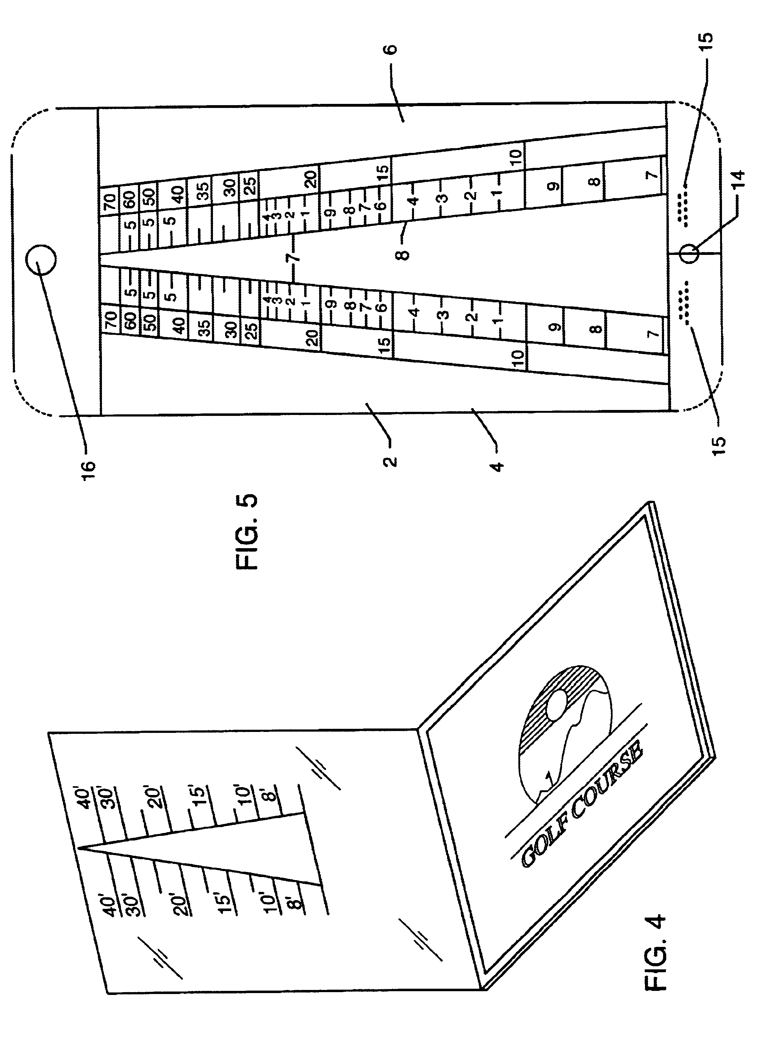
(FIG. 4): A third embodiment, shown in FIG. 4, is a card member and triangle-shaped opening in accordance with the preferred embodiment that forms the cover of a golfer's scorecard. The cover is made of a clear plastic sheet and adapted to slip over a scorecard. By opening the cover, a golfer views the cup through the triangular opening. The range finder is then used as described above.

fourth embodiment

A fourth embodiment is a card member in accordance with the preferred embodiment having a triangular opening and, in addition, an arm positioned on one long side of the triangle and affixed in or to the card member. The arm is made to slide across the opening from one side and thereby narrow its dimensions. This allows the device to adjust, where appropriate, for use by persons of different heights and / or arm lengths while using the same markings.

(FIGS. 5 and 6): A fifth embodiment, as shown in FIGS. 5 and 6, is a range finder 2 in accordance with the preferred embodiment having a card-like member 4, where a first portion 6 is opaque and defines a generally triangular-shaped window 8 or opening through which a person can view an object. In addition, two movable arms 17, each positioned along each leg of the triangular-shaped opening and affixed to the top portion of the card member 4 by some fastening unit at a specified pivot point 16 on the back of the card-like member 4 or within...

sixth embodiment

A sixth embodiment is a first member having a v-shaped opening with a vertex having an included angle of between 5 degrees and 20 degrees but preferably 12 degrees. Lines and numerals are expressed on or adjacent to the edges or prongs of the opening. While this structure could be incorporated into innumerable devices, the following additional, exemplary embodiments are described as embodiments seven through ten:

(FIG. 7): A seventh embodiment of the invention is shown in FIG. 7 wherein a conventional golf glove has been modified to incorporate a range finder in accordance with this invention. As illustrated a golf glove 50 includes a back portion 51 which covers the back of a golfer's hand. The glove 50 also includes a tab portion 52 with a Velcro fastener or the like on one side thereof for snugly fastening the glove about the hand of a golfer in a customary manner. A palm portion (not shown) and back portion 51 are connected by seams and sections which correspond to the parts of t...


PUM


Abstract

A low-cost-of-manufacture, portable, capable-of-adjustment range finder for estimating distances between the user and one or more objects with a known width, height or other linear dimension (such as a cup on a putting green, a target for target shooting, a military vehicle, etc.) is disclosed. In each of its embodiments, the invention relates to, and relies on, the fact that the image of an object appears to decrease in size as distance increases. In the preferred embodiment, an opening is formed through which to view the object, and recorded information is expressed on, in or included with the device so that the user can correlate the position of the object image to predetermined distance information. The shape and size of the opening are reasonably variable, but, once the size and shape are determined, the position of the distance information is fixed at the position on the opening where the image size corresponds to the indicated distance. This range finder is also capable of measuring distances from the user to a variety of objects by using the same device, to objects at short distances, to small objects and to objects at ground level.

Description

This invention relates to range finders, specifically to a range finder that relies on the reduction in the size of an object's image as distance increases, as viewed through an opening in the range finder, to determine the object's distance from the user where the object's width, length, height or other visible linear dimension is known or can be estimated.PRIOR ARTThere has been a long-standing need for "range finders," ie., devices that allow the user to gauge his or her distance from an object without physically measuring the distance. Although various devices have been utilized for this purpose, two categories of range finder are relevant here: (1) "image-based" range finders that use the decrease in size of an object's image as distance increases to determine what that distance is; and (2) devices that can bounce a signal or beam off a target object, such as sonar, radar and laser range finders. The instant invention is an image-based range finder that improves upon the prior ...

Claims


Application Information

Patent Timeline
IPC IPC(8): G01C3/00G01C3/22
CPCG01C3/22
Inventor FAULKNER, ROBERT L.FAULKNER, ROBERT P.
Owner FAULKNER ROBERT L
Learn More