Apparatus and method for thin profile ratchet actuator

a ratchet actuator and thin profile technology, applied in the direction of mechanical control devices, instruments, chairs, etc., can solve the problem of inconvenient angle protruding from the corresponding lever position

Inactive Publication Date: 2003-10-28
L & P PROPERTY MANAGEMENT CO
View PDF60 Cites 26 Cited by
  • Summary
  • Abstract
  • Description
  • Claims
  • Application Information

AI Technical Summary

Problems solved by technology

However, once a user selects a position for a device such as a lumbar support, the corresponding lever position frequently protrudes at an inconvenient angle.
In automobiles, this can be particularly problematic in that clothing, seat belts and the like are easily caught on a lever that protrudes from the seat back where such levers are usually mounted.

Method used


Image

  • Apparatus and method for thin profile ratchet actuator
  • Apparatus and method for thin profile ratchet actuator
  • Apparatus and method for thin profile ratchet actuator

Examples


Embodiment Construction

Ergonomic Mechanism Operation

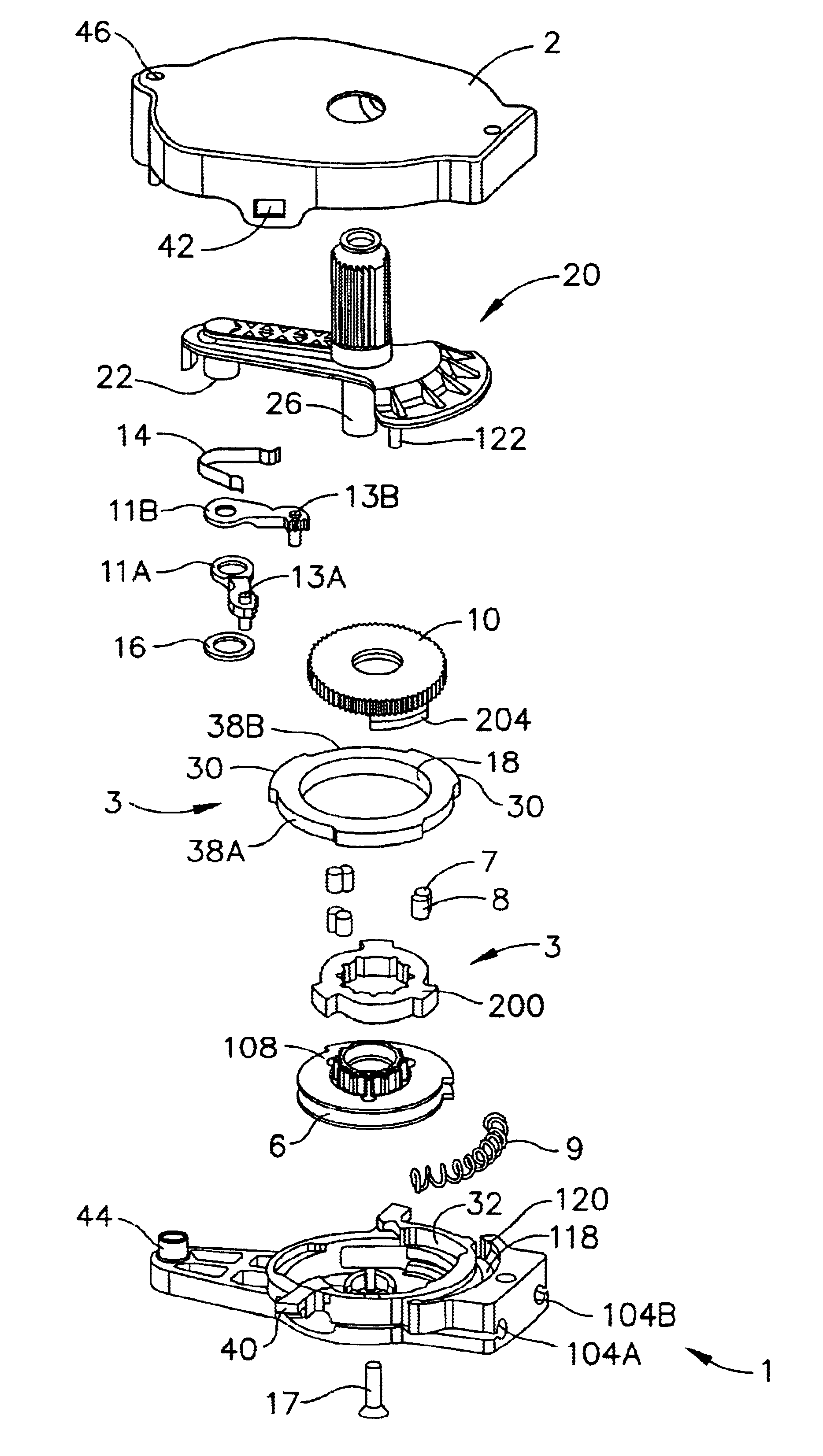
Referring to the figures where like reference numbers indicate like elements, FIG. 1 is a perspective view of a typical ergonomic device--a lumbar support--with a lever actuator like the ratchet actuator of the present invention installed. Lumbar support, 50, has a fixed portion, 52, and an arching portion, 54. Guide rails, 56, are mounted to a seat frame (not shown) with mounting mechanisms, 58. A plurality of lateral elements, 60, span the archable portion of the lumbar support and, in the pictured example, lateral elements, 62, also traverse the fixed portion, 52, of the lumbar support.

Also disposed on guide rails, 56, are two brackets comprised of a fixed lower bracket, 64, and sliding upper bracket, 66. Two archable pressure surfaces, 68, in this case metal rods, run generally vertically and, when flat, are generally parallel to guide rails, 56. The archable pressure rods, 68, are pivotally mounted to the upper bracket at pivot mounts, 70, and pivot...


PUM


Abstract

A ratchet actuator for an ergonomic device has a thin profile due to the combination of multiple functions into single parts. A ratchet drive gear also has drive fingers for operating a clutch. A clutch stator has high and low steps for engaging and disengaging ratchet pawls.

Description

None1. Field of the InventionThe present invention is in the field of mechanical actuators, particularly tension or traction device actuators, especially as used in automotive or furniture ergonomic mechanisms such as lumbar supports.2. Prior ArtErgonomic mechanisms such as lumbar supports are typically adjustable by mechanical means which may be activated and controlled at certain expense by motors, and at a lesser expense by levers, handwheels and the like. There is a continuing need for simplicity, durability and cost control in this area.Ergonomic mechanisms are commonly designed to retain particular settings chosen by a repeat user for his or her individual comfort. Retaining an adjustment is often achieved by keeping a device like a lumbar support under pressure or tension, as by a traction cable. Settings need to be maintained through loading and unloading cycles, requiring brakes or locks for holding the settings. Serial adjustment must remain possible, requiring releases, o...

Claims


Application Information

Patent Timeline
Patent Type & Authority Patents(United States)
IPC IPC(8): A47C7/46A47C3/025A47C3/02B60N2/44B60N2/235G05G5/06G05G5/00B60N2/90
CPCB60N2/2354B60N2/444G05G5/06B60N2/4445Y10T74/2133B60N2/938B60N2/943
Inventor LIU, JINTAOSTADLBAUER, ALFRED
Owner L & P PROPERTY MANAGEMENT CO
Why Eureka
Try Eureka