Image forming apparatus

a technology of forming apparatus and forming head, which is applied in the direction of gearing details, electrographic processes, instruments, etc., can solve the problems of affecting the speed of movement, affecting the stability of the moving speed of the moving head, and affecting the service life of the forming head

Inactive Publication Date: 2003-10-28
CANON KK
View PDF1 Cites 43 Cited by
  • Summary
  • Abstract
  • Description
  • Claims
  • Application Information

AI Technical Summary

Problems solved by technology

In such a product, the long-term use thereof causes the seam to break.
Recently, however, seamless transfer belts have come to be manufactured and the lengthening of their service life has been advanced.
Slight slippage is caused during the movement of the transporting belt, and the moving speed thereof becomes unstable.
Particularly, in the case of a tandem type image forming apparatus provided with multiple sets of photosensitive members for the respective colors of the toners, if the moving speed of the transporting belt is unstable, toner images of the respective colors are not correctly superimposed one upon another, with a result that so-called color misregistration occurs and the quality of image is remarkably deteriorated.
As the endurance change further progresses, the transporting belt becomes incapable of being driven.
Also, when the volume resistivity of the transporting belt is changed by the filming phenomenon of the toners on the inner surface of the transporting belt, it will present itself as an uneven image and a good image cannot be obtained.

Method used


Image

  • Image forming apparatus
  • Image forming apparatus
  • Image forming apparatus

Examples


embodiment 1

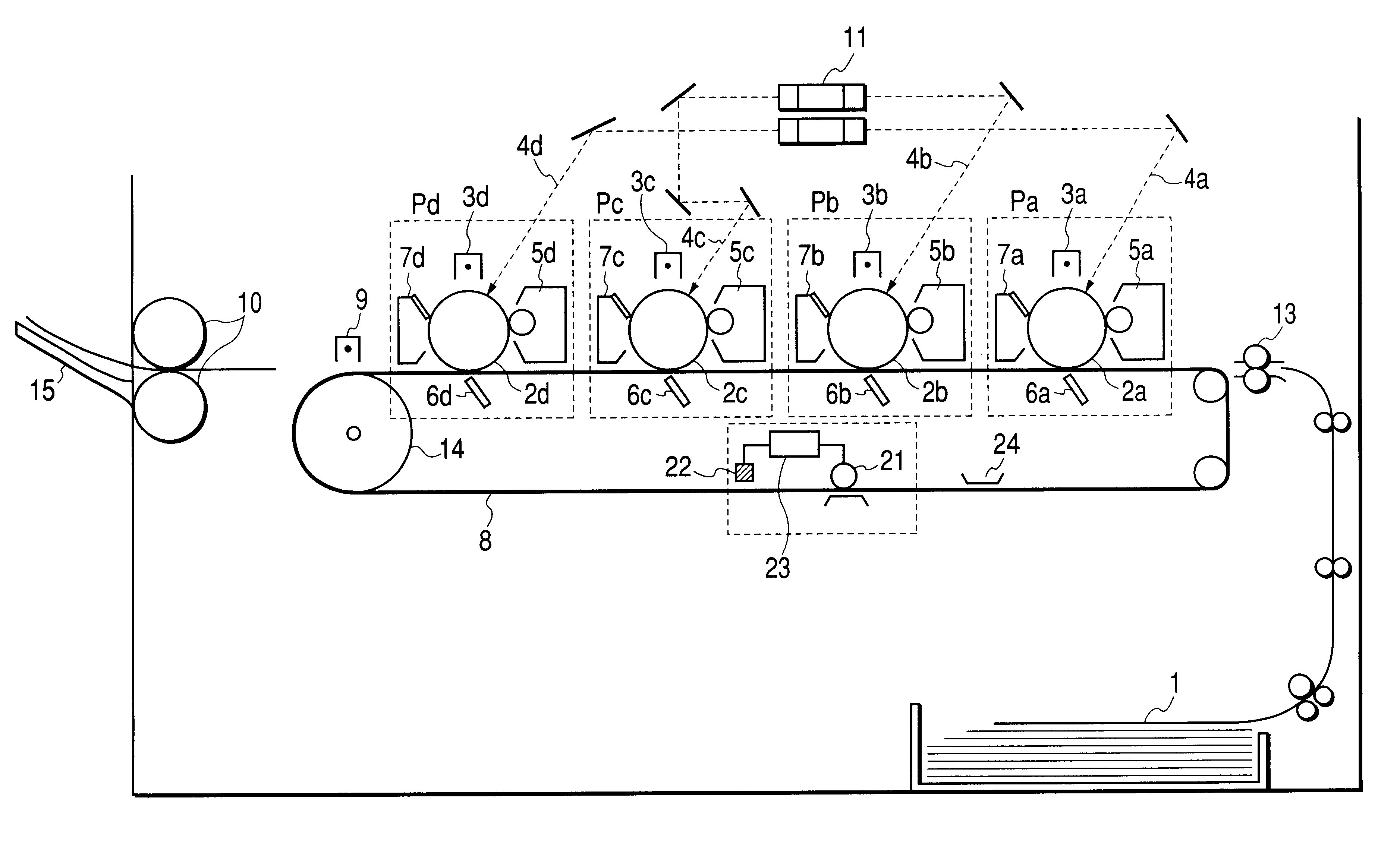
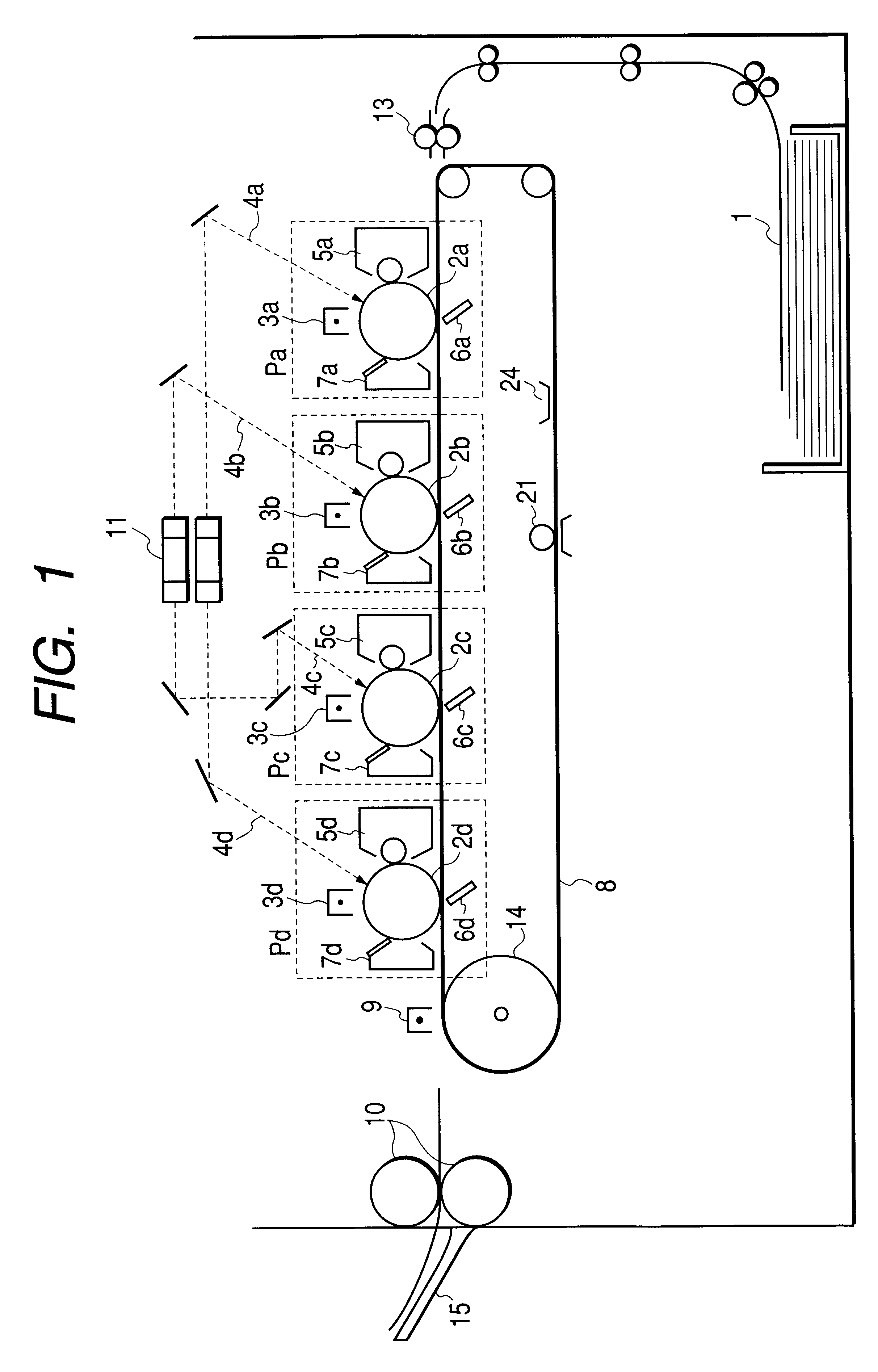
FIG. 1 schematically shows the construction of an image forming apparatus of the present invention. In FIG. 1, first, second, third and fourth image forming portions, Pa, Pb, Pc and Pd, are juxtaposed in the image forming apparatus, and cyan, magenta, yellow and black toner images are successively formed by way of latent image forming, developing and transferring processes.

The image forming portions Pa, Pb, Pc and Pd are provided with electrophotographic photosensitive drums 2a, 2b, 2c and 2d, respectively, which are image bearing members exclusively for use therewith, and a transfer belt 8, which is a recording material bearing member, is installed adjacent to the photosensitive drums 2a, 2b, 2c and 2d, and toner images of the respective colors formed on the photosensitive drums 2a, 2b, 2c and 2d are transferred onto a recording material 1 borne and transported by the transfer belt 8. The recording material 1, onto which the toner images of the respective colors have been transfer...

embodiment 2

Embodiment 2 of the present invention will now be described with reference to FIGS. 7 and 8.

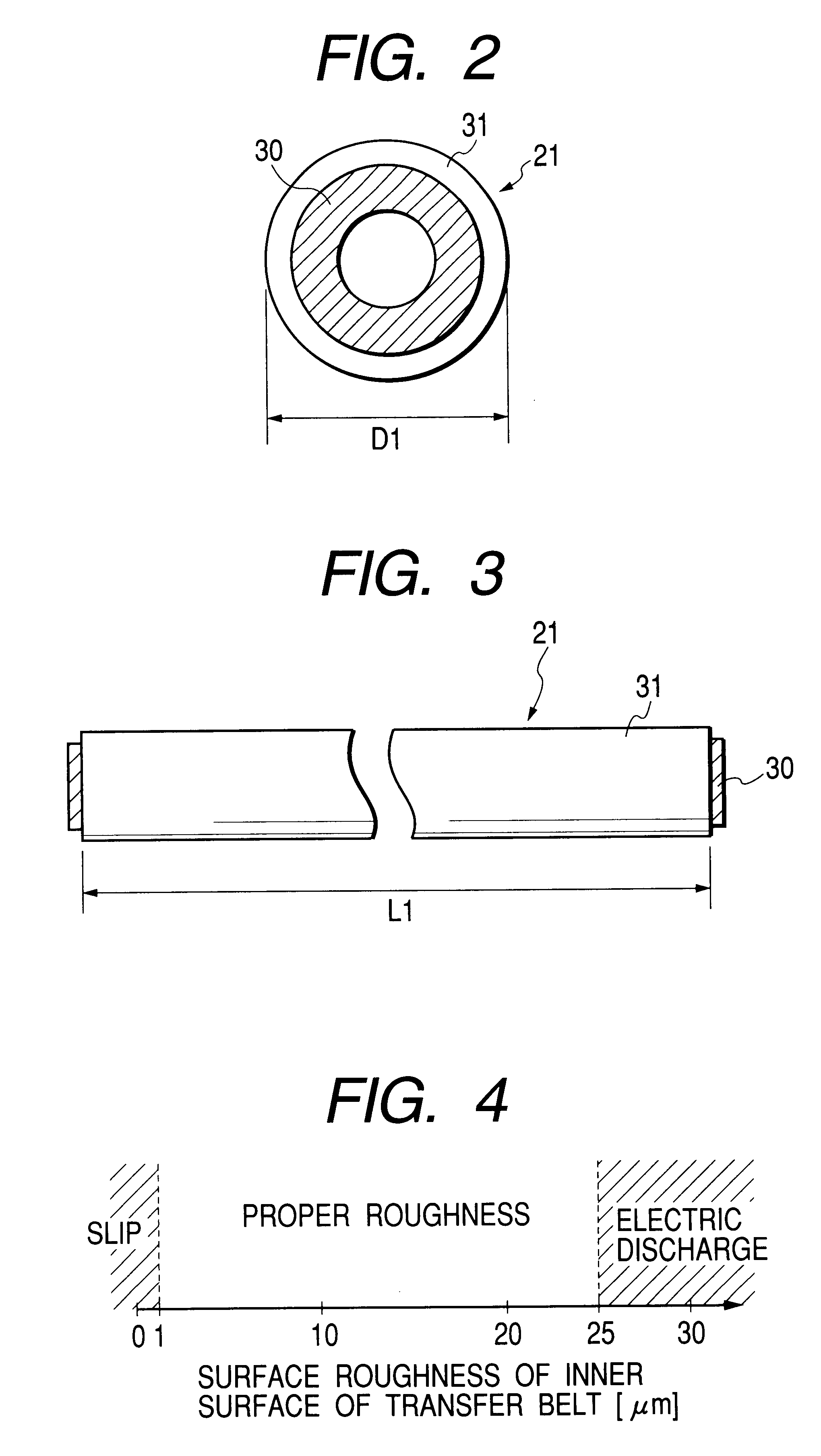
In the embodiment, detecting means 22 for detecting the surface roughness of the inner surface of the transfer belt 8 is provided upstream of the abrasive roller 21 in the direction of rotation of the transfer belt.

Design is made such that when it is detected that the surface roughness of the inner surface of the transfer belt 8 is smaller than a predetermined value, a signal is output by a control device 23 connected to the detecting means 22 so that the abrasive roller 21 may contact the inner surface of the transfer belt 8. When an image forming operation is terminated, the abrasive roller 21 effects the abrasion of the inner surface of the transfer belt 8 so as to make the inner surface of the transfer belt 8 have predetermined roughness.

During operation of the abrasive roller 21, the main body of the apparatus enters its standby state, so that an image forming operation cannot be perform...


PUM


Abstract

In an image forming apparatus wherein the slip of a transporting belt relative to a driving device due to a change in the surface state the inner surface of the transporting belt and a bad image can be reliably prevented, and having a photosensitive drum on the surface of which a toner image is formed, a transfer belt and a driving roller for driving the transfer belt, wherein the toner image formed on the surface of the photosensitive drum is transferred onto the transfer belt or a recording material borne on the transfer belt, an abrasive roller is provided at a position, in contact with a surface on which the driving roller abuts against the transfer belt.

Description

1. Field of the InventionThe present invention relates to an image forming apparatus for forming a toner image on a photosensitive member, and transferring the toner image to a transporting belt or a recording material borne on the transporting belt to thereby obtain an image.2. Description of Related ArtThere have heretofore been proposed various image forming apparatuses which are provided with a plurality of image forming portions, wherein toner images of different colors are formed in the respective image forming portions, and the toner images then are sequentially superimposed and transferred onto the same recording material to thereby form a color image. For high-speed recording, use is made of a color copier of the multi-color electrophotographic type using an endless transfer belt.There also have been proposed various image forming apparatuses of the intermediate transfer type, in which toner images first are transferred onto an intermediate transfer member, and thereafter a...

Claims


Application Information

Patent Timeline
Patent Type & Authority Patents(United States)
IPC IPC(8): G03G15/16B65H5/02G03G15/00
CPCG03G15/1605G03G15/167G03G2215/0119G03G15/161
Inventor SUZUKI, SHINYAOMATA, HARUHIKO
Owner CANON KK
Why Eureka
Try Eureka