Reversible ratchet-type wrench

a ratchet-type wrench and ratchet-type technology, which is applied in the direction of wrenches, manufacturing tools, spanners, etc., can solve the problems of troublesome disengagement of ring spanners, increased manufacturing cost and assembly time, and inability to operate ring spanners in reverse directions

Inactive Publication Date: 2003-11-11
HU BOBBY
View PDF183 Cites 43 Cited by
  • Summary
  • Abstract
  • Description
  • Claims
  • Application Information

AI Technical Summary

Problems solved by technology

However, the ring spanners could not be operated in a reverse direction and thus require troublesome disengagement of the ring spanner from the fastener and reengagement of the ring spanner until tightening/loosening of the fastener is achieved.
The overall structure has increased number of elements such that the manufacture cost and the assembling time are both increased.
However, drilling a pin hole for mounting the pin would be extremely difficult for a size 8 mm wrench, and the pin hole weakens the structure of the head of the wrench.
Precise processing of the pin hole is required to avoid adverse affection to the sliding and positioning of the stop block in the receiving compartment, which increases the rate of disqualified products and the manufacture cost.
Further,

Method used


Image

  • Reversible ratchet-type wrench
  • Reversible ratchet-type wrench
  • Reversible ratchet-type wrench

Examples


first embodiment

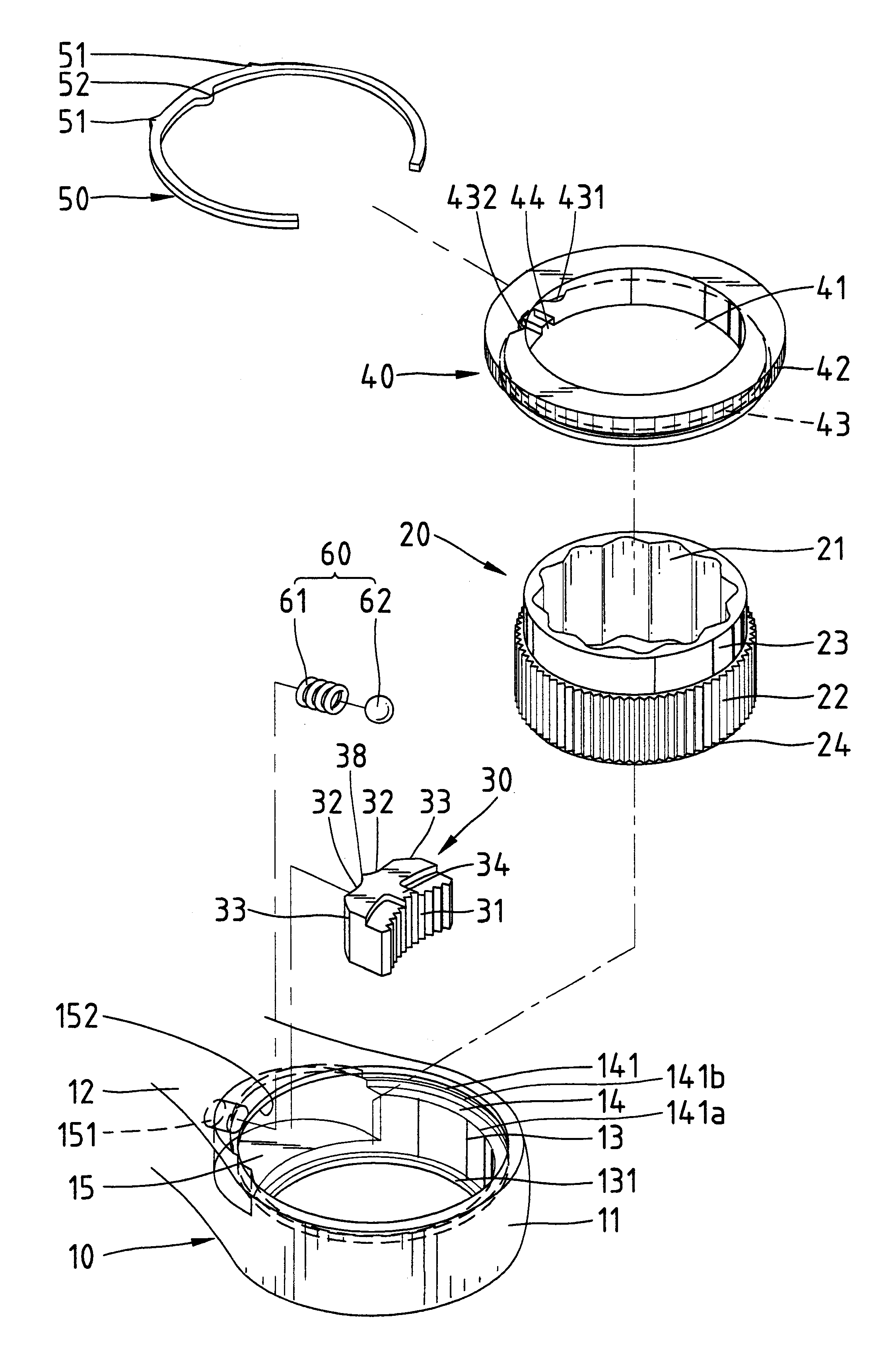
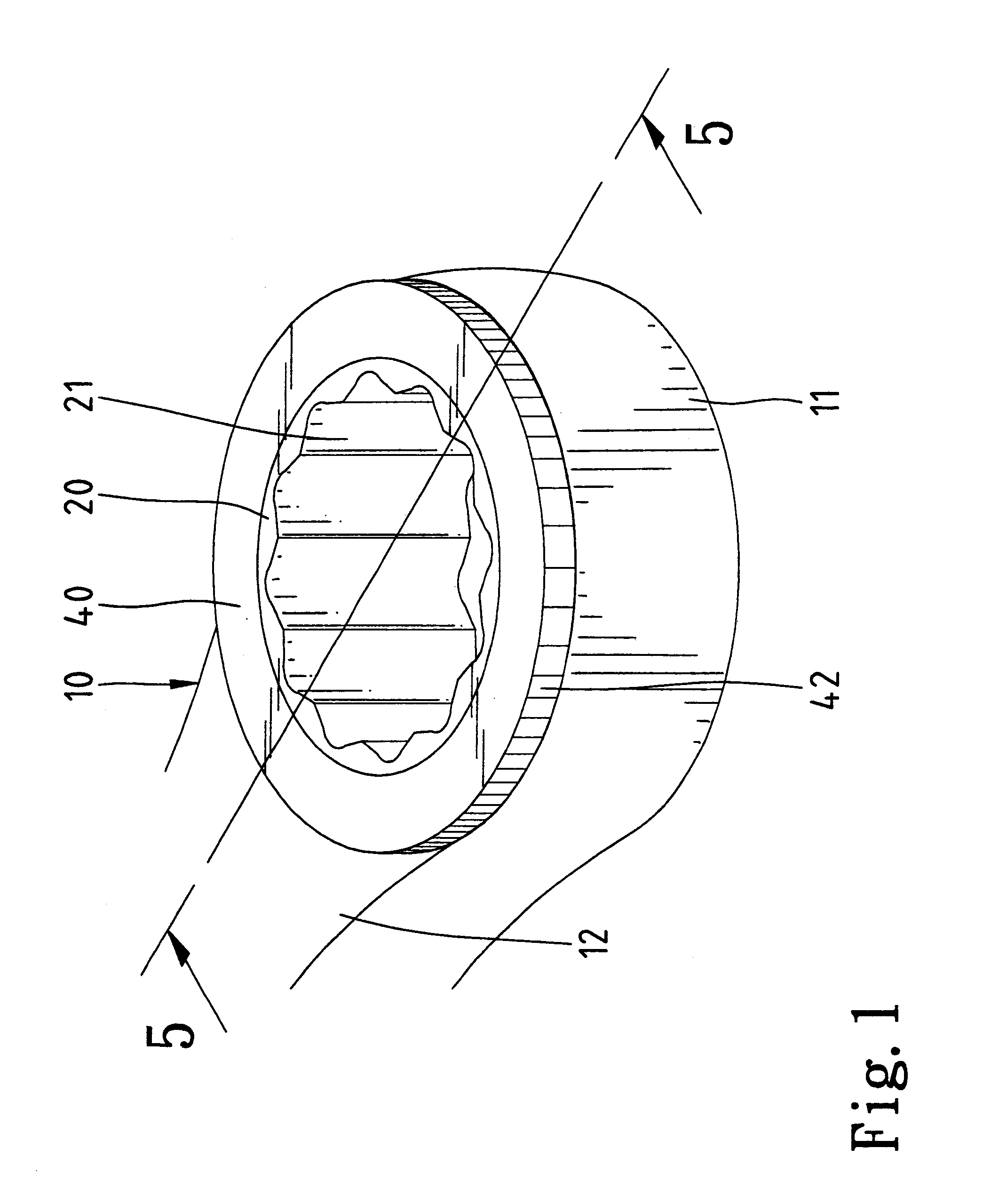
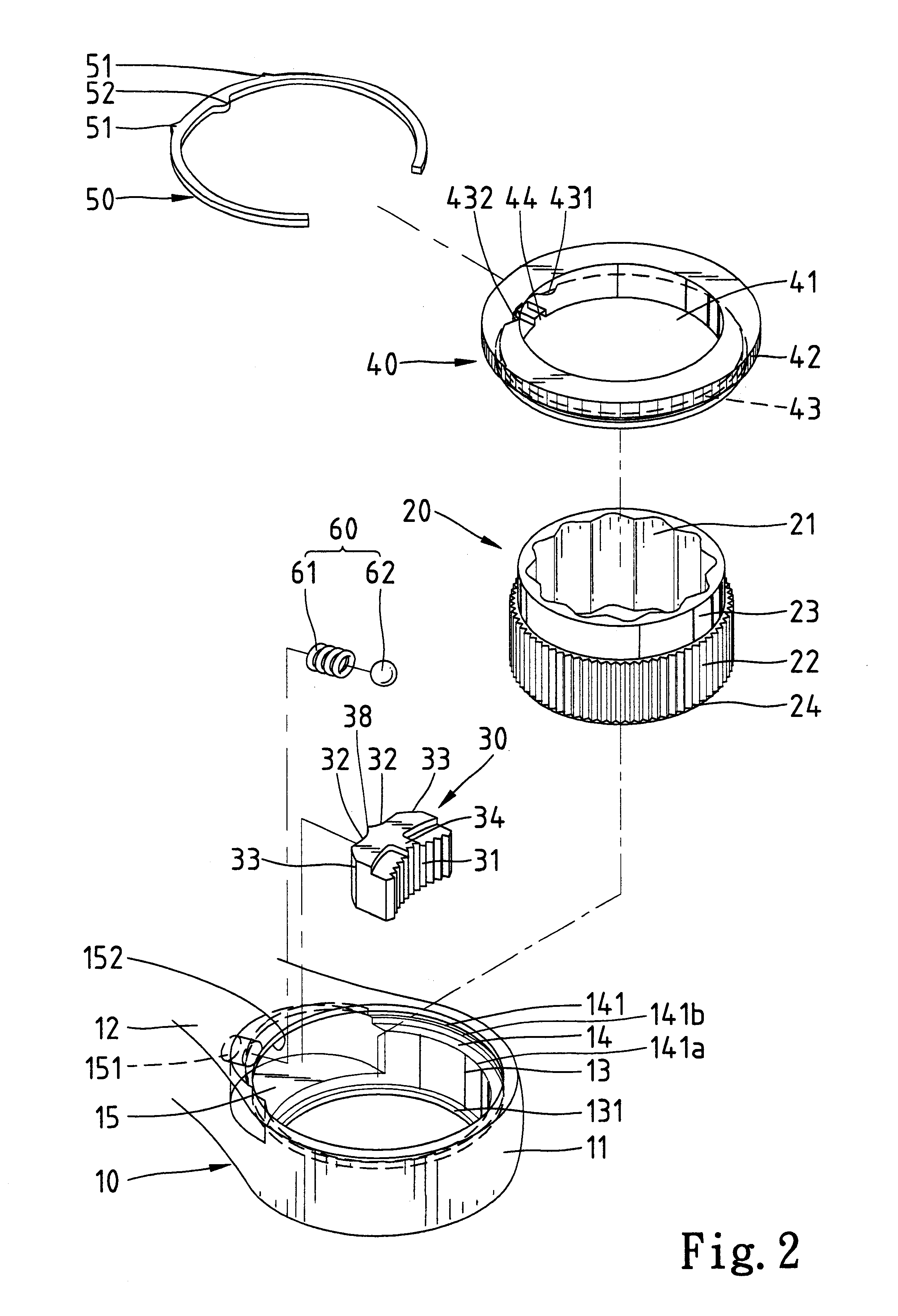
Referring to FIGS. 1 through 3, a ratchet-type reversible wrench in accordance with the present invention is designated by "10" and generally comprises a handle 12 and a head 11 extending from the handle 12. A hole 13 is defined in the head 11 and a stepped portion 14 is formed on an end (the upper one in FIG. 2) of a peripheral wall defining the hole 13. Preferably, the diameter of an inner section 141a of the stepped portion 14 is greater than that of an outer section 141b of the stepped portion 14 for easy installation of a switching member (e.g., a switching ring 40), which will be described later. An annular groove 141 is defined in a wall defining the outer section 141b of the stepped portion 14. A compartment 15 is defined in a peripheral wall defining the hole 13, and a cavity 151 is defined in a wall defining the compartment 15. An annular ledge 131 projects inward from the other end (the lower one in FIG. 2) of the peripheral wall defining the hole 13. Further, an end (the...

second embodiment

FIGS. 13-18 illustrate the invention, wherein like numerals denote like elements. In this embodiment, the stepped portion 152 of the compartment 15 is omitted, and the upper end of the compartment 15 is partially coincident with the stepped portion 14, best shown in FIG. 14. The protrusion 34 of the pawl 30 is located at a level lower than an upper side of the pawl 30; namely, the height of the left portion of the pawl 30 in FIG. 13 is increased in response to the change in the height of the compartment 15. Thus, the engaging area between each pressing end 33 of the pawl 30 and the wall defining the compartment 15 is increased to thereby enhance the pressing effect. The outer protuberances 51 of the retainer ring 50 are respectively positioned by two ends of the upper portion of the compartment 15 to thereby retain the retainer ring 50 in the wrench 10, best shown in FIG. 16. The inner protuberance 52 of the retainer ring 50 is engaged in, e.g., the first retaining section 431 of th...

third embodiment

FIGS. 19-24 illustrate the invention, wherein like numerals denotes like elements. In this embodiment, the stepped portion 152 of the compartment 15 is omitted, and a positioning hole 153 is defined in a central portion of the upper portion of the wall defining the compartment 15, best shown in FIGS. 20 and 21. Further, the retainer ring 50 has a positioning protuberance 53 on the outer periphery thereof to replace the two outer protuberances 51 in the above embodiments. The positioning protuberance 53 is slidably received in the positioning hole 153 to prevent rotation of the retainer ring 50 relative to the wrench 10. As illustrated in FIG. 22, a gap 55 is defined between a section of the retainer ring 53 from which the outer protuberance 51 projects outward. The positioning hole 153 is longer than the positioning protuberance 53.

Referring to FIG. 22, when switching of the ratcheting direction of the wrench 10 is required, the switching ring 40 is turned, e.g., clockwise, since a ...


PUM


Abstract

A wrench comprises a handle and a head extending from the handle. A peripheral wall defining a hole in the head includes a compartment. An annular groove is defined in an end of the peripheral wall defining the hole. The annular groove is partially coincident with the compartment. A pawl is slidably received in the compartment and biased to engage with a gear wheel in the hole. A switching member is partially mounted in the hole for moving the pawl when switching of the ratcheting direction is required. A retainer ring is partially engaged in an annular groove in the switching member and partially engaged in the annular groove of the head. The retainer ring is retained in place by a wall defining the compartment. The switching member is not moved when the pawl moves as a result of free rotation of the wrench.

Description

1. Field of the InventionThe present invention relates to a reversible ratchet-type wrench. In particular, the present invention relates to a ratchet-type wrench that allows reversible operations without sacrificing the strength of the wrench.2. Description of the Related ArtWrenches are an important hand tool and have many types such as spanners, adjusting wrenches, combination wrenches, and socket wrenches. Ring spanners are very useful when the fastener to be tightened / loosened is located in a difficult-to-access place. However, the ring spanners could not be operated in a reverse direction and thus require troublesome disengagement of the ring spanner from the fastener and reengagement of the ring spanner until tightening / loosening of the fastener is achieved. U.S. Pat. No. 6,044,731 to Hsieh issued on Apr. 4, 2000 discloses a double-reversible ratchet wrench that modifies the box end of a ring spanner so as to allow reversible operation of the spanner in both directions. The ra...

Claims


Application Information

Patent Timeline
IPC IPC(8): B25B13/00B25B13/46
CPCB25B13/463B25B13/461
Inventor HU, BOBBY
Owner HU BOBBY
Why Eureka
Try Eureka