Hammer drill

a hammer drill and hammer head technology, applied in the field of hammer drills, can solve the problems of vibration in the main body of the hammer drill, deterioration of the striking force transmitting performance, and adverse influence on the behavior of the drill head, and achieve the effect of suppressing vibration

Inactive Publication Date: 2003-11-11
KOKI HLDG CO LTD
View PDF6 Cites 64 Cited by
  • Summary
  • Abstract
  • Description
  • Claims
  • Application Information

AI Technical Summary

Benefits of technology

In view of the problems of the above-described prior art, the present invention has an object to provide a reliable mechanism for preventing the non-load continuous striking operation of a hammer drill which is capable of suppressing vibration and assuring a long-lasting life.

Problems solved by technology

The presence of this kind of offset gives adverse influence to the behavior of the reciprocative motion of the intermediate member which is driven by the striking member.
The striking force transmitting performance deteriorates.
The striking force dispersing toward the circumferential portions of the intermediate member will cause vibration in the main body of the hammer drill.
Providing such a clearance tends to enlarge the fluctuation of the intermediate member.

Method used


Image

  • Hammer drill
  • Hammer drill
  • Hammer drill

Examples


Embodiment Construction

Preferred embodiments of the present invention will be explained with reference to attached drawings. Identical parts are denoted by the same reference numerals throughout the views.

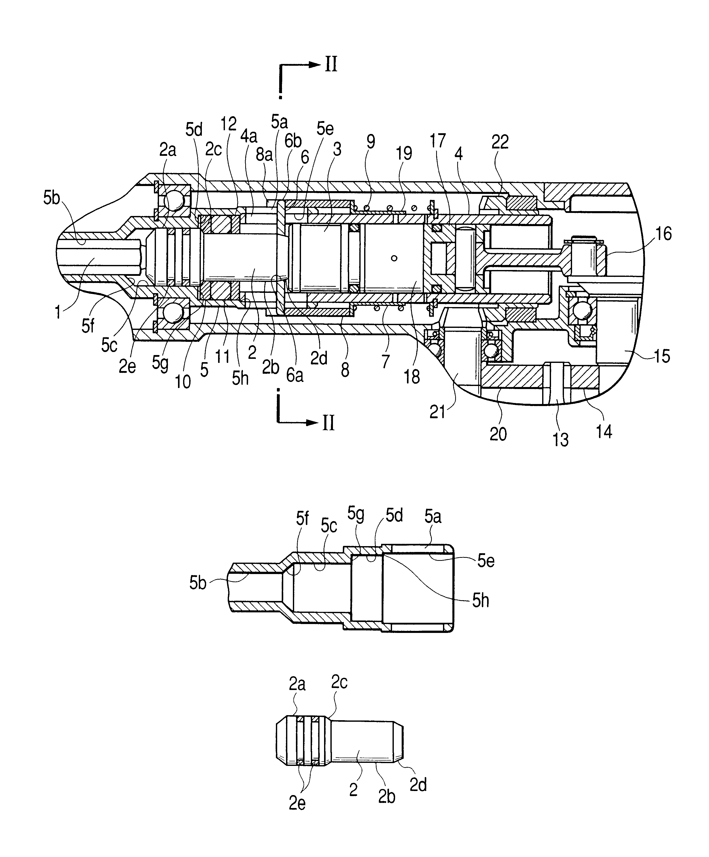
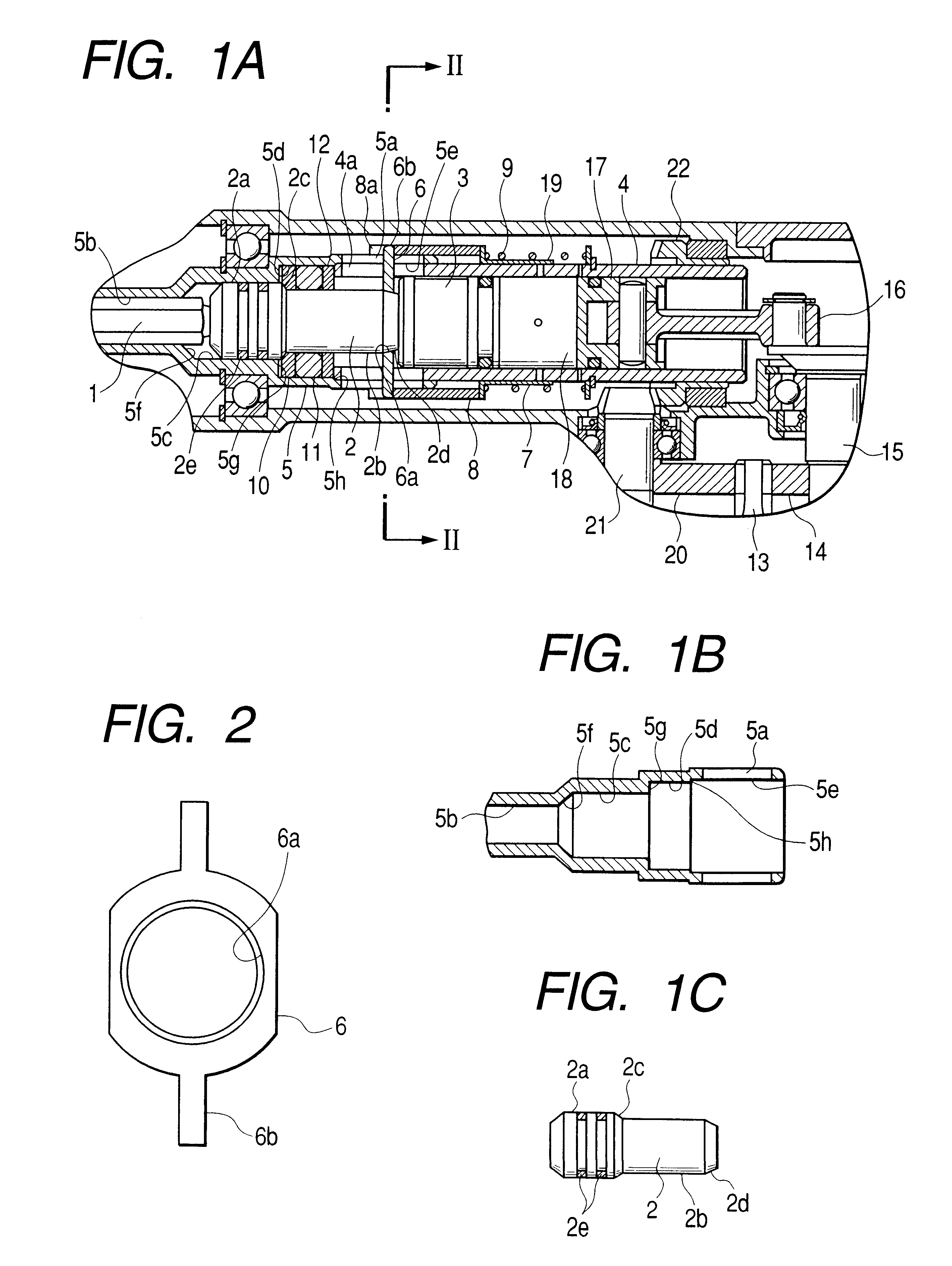
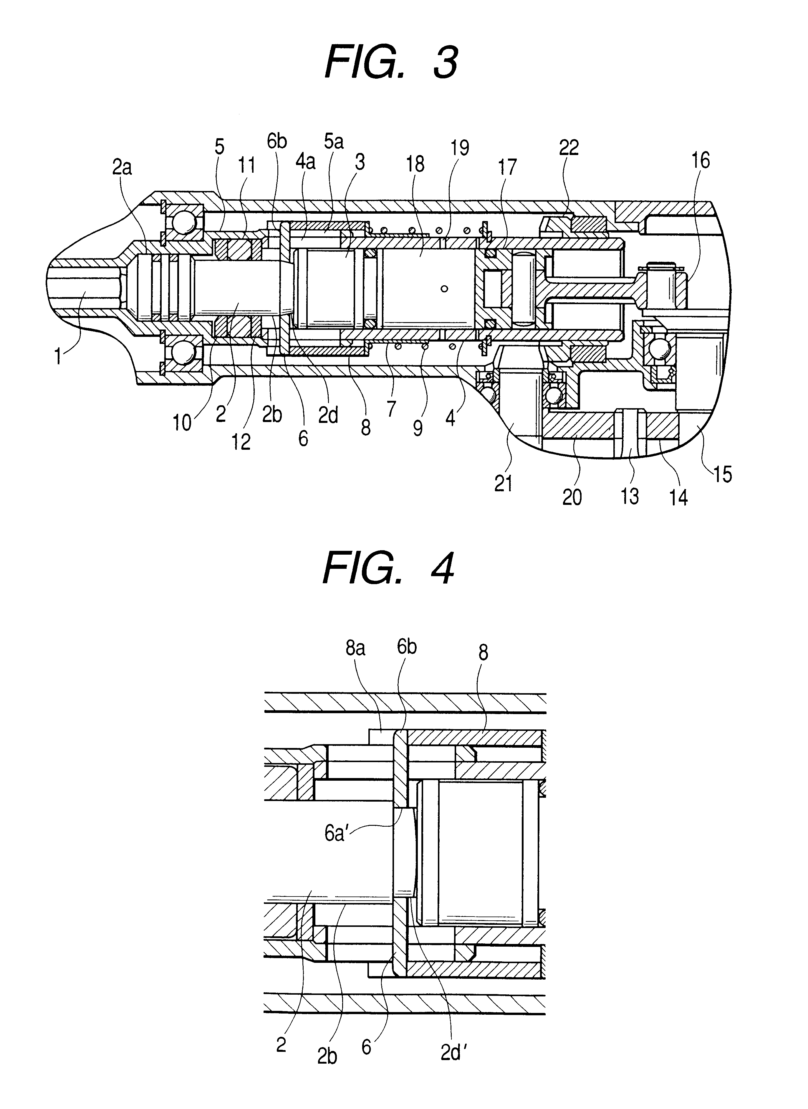
FIGS. 1A to 3 show a hammer drill in accordance with a preferred embodiment of the present invention.

As shown in the drawings, the hammer drill of this embodiment includes a motor (not shown) equipped with a pinion 13. The pinion 13 serves as an output shaft of the motor. A first gear 14 meshes with the pinion 13 to transmit the rotational motion of the motor to a crank shaft 15. The crank shaft 15 thus rotates in response to the rotation of the motor. A connecting rod 16 has one end engaged with the crank shaft 15. The other end of the connecting rod 16 is connected to a piston 17 which is slidably accommodated in a cylinder 4. The piton 17 reciprocates in the axial direction of the cylinder 4. In this manner, the rotational motion of the motor is converted into the reciprocative motion of the piston 17...


PUM

PropertyMeasurementUnit
axial lengthaaaaaaaaaa
diameteraaaaaaaaaa
striking forceaaaaaaaaaa

Abstract

An engaging portion, formed at an axial end of an intermediate member, is engageable with a slide sleeve. A cylinder has an elongated hole with an axial length longer than a shifting distance of the intermediate member. The slide sleeve includes an annular member and a slide member. The annular member has an inner cylindrical wall engageable with the engaging portion of the intermediate member and a projection extending in a radially outward direction passing through the elongated hole beyond an outer surface of the cylinder. The slide member is coupled around the outer surface of the cylinder and is slidable in the axial direction of the cylinder. One axial end of the slide member, positioned closer to a working tool, is engaged with the projection of the annular member. The other axial end of the slide member is urged toward the working tool by an urging member.

Description

BACKGROUND OF THE INVENTIONThe present invention relates to a hammer drill and more particularly to a mechanism for preventing a striking member of the hammer drill from continuing the non-load striking motion.A conventional hammer drill includes a striking force transmitting mechanism and a rotational motion transmitting mechanism. The striking force transmitting mechanism converts a rotational motion of a motor into a reciprocative motion of a piston slidably accommodated in a cylinder. A striking member is positioned in the cylinder and is axially offset from the piston via an air chamber. The striking member slides in the cylinder in response to the reciprocative movement of the piston. An intermediate member abuts a working tool detachably held in a tool holder. The striking member strikes the intermediate member. The rotational motion transmitting mechanism transmits the rotational motion of the motor to the working tool via the cylinder and the tool holder. The intermediate m...

Claims


Application Information

Patent Timeline
Patent Type & Authority Patents(United States)
IPC IPC(8): B25D16/00B23B45/16B25D17/10B25D11/12
CPCB25D16/00B25D2211/068B25D2211/003
Inventor HAGA, HIROSHI
Owner KOKI HLDG CO LTD
Why Eureka
Try Eureka