
Automatic air conditioner having learning function and control method of control system

a technology of automatic air conditioner and function, which is applied in the field of vehicle air conditioner, can solve the problems inability to learn the function of manual adjustment of air blowing amount, and inability to meet the passenger's request for reducing air blowing amoun

Inactive Publication Date: 2003-11-11
DENSO CORP
View PDF9 Cites 20 Cited by
  • Summary
  • Abstract
  • Description
  • Claims
  • Application Information

AI Technical Summary

Benefits of technology

It is another object of the present invention to provide a control method of a control system, which changes correction of control characteristic of the air blowing amount by effectively learning manual operation.
Preferably, the automatic control characteristic has a first control portion in the first area and a second control portion in the second area, the control device changes the correction of the automatic control characteristic to correct the first control portion when the condition value satisfies a predetermined condition in a relationship with a threshold value stored in the control device, and the control device changes the correction of the automatic control characteristic to correct the second control portion when the condition value does not satisfy the predetermined condition in the relationship with the threshold value. Further, the condition value can be at least one of an air temperature in the passenger compartment, a target blowing temperature of air to be blown into the passenger compartment, a passed time from a start of automatic control operation, an estimated value of a passenger's thermal feeling, and a skin temperature of the passenger. Accordingly, the manual operation can be effectively learned so that the blowing amount control characteristic after the manual operation can be fitted to the passenger's preference.
More preferably, the second area includes a low blowing amount area, and an intermediate blowing amount area where the air blowing amount is between the low blowing amount area and the first area. In this case, when the control device corrects the second control portion, the control device corrects at least one of the switching point at which the air blowing amount is switched between the first area and the intermediate blowing amount area, a change ratio of the air blowing amount in the intermediate blowing amount area, and the air blowing amount in the low blowing amount area. Accordingly, even in the low blowing amount area, the passenger's preference manual operation can be effectively learned.
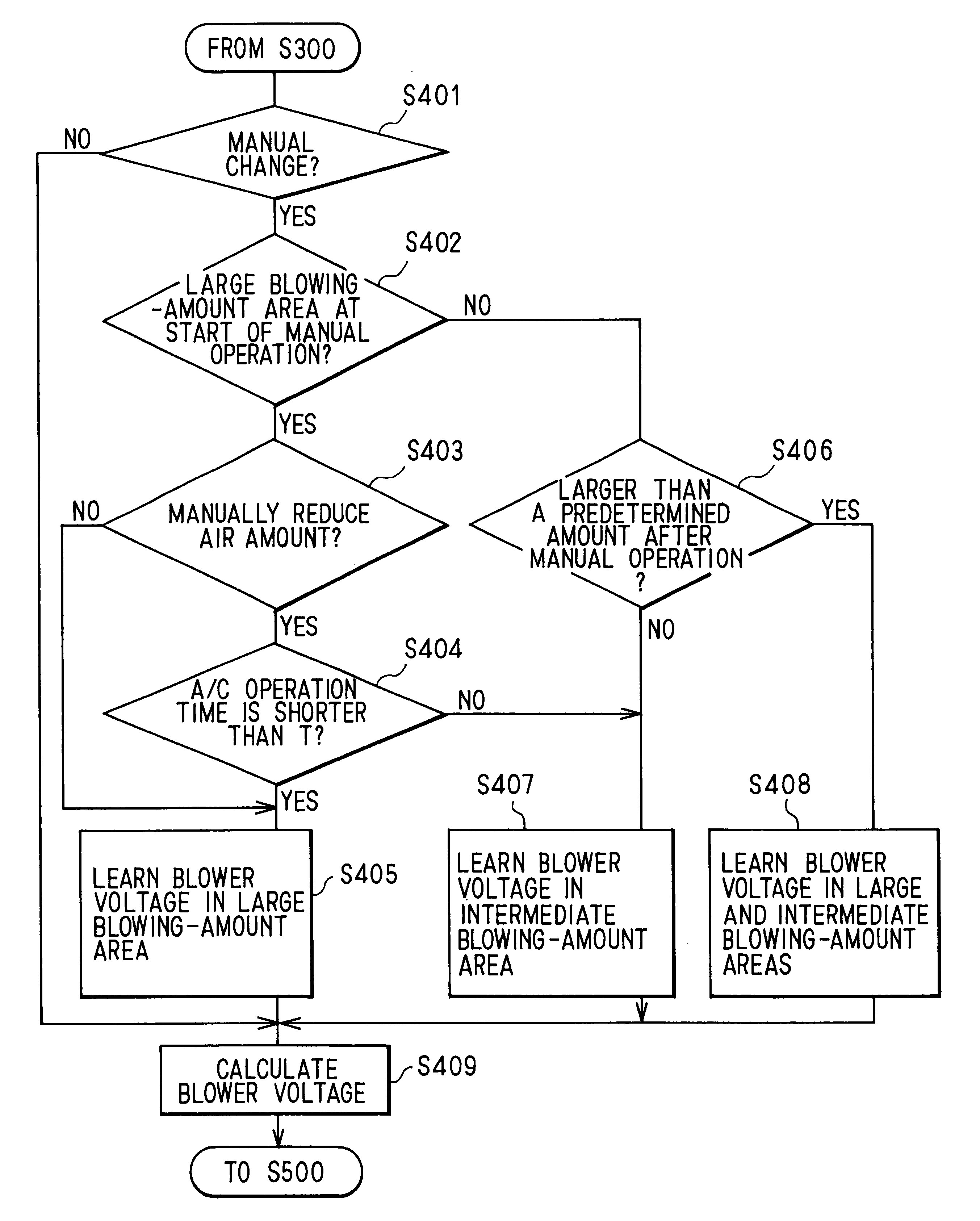
On the other hand, in a control method of a control system for a vehicle air conditioner, it is determined whether the air blowing amount at a start time of manual change is in the first area when the air blowing amount is manually changed. Further, in learning of the control method, the air blowing amount in the first area is reduced when the temperature relative to the inside air temperature is lower than a predetermined temperature when the air blowing amount is manually reduced in the first area and a condition value is in a first state. Further, in the learning, the air blowing amount in the second area is reduced when the air blowing amount is manually reduced in the first area when the condition value is in a second state. Accordingly, the control method of the control system changes the correction of the control characteristic of the air blowing amount by effectively learning manual operation.

Problems solved by technology

However, in the vehicle air conditioner disclosed in JP-A-3-54015, the air blowing amount in the large blowing amount area of the automatic control cannot be changed, thereby not being satisfied to the passenger's request for reducing the air blowing amount in the large blowing amount area.
Therefore, the air blowing amount becomes deficient in the initial time of the next cool-down operation.
On the other hand, when the air blowing amount is manually changed in a blowing amount control area except for the large blowing amount area, the manually-changed air blowing amount cannot be learned.
Therefore, the air amount to be blown into a passenger compartment is not fitted to the passenger's preference in the blowing amount control area except for the large blowing amount area.

Method used


Image

  • Automatic air conditioner having learning function and control method of control system
  • Automatic air conditioner having learning function and control method of control system
  • Automatic air conditioner having learning function and control method of control system

Examples


first embodiment

(First Embodiment)

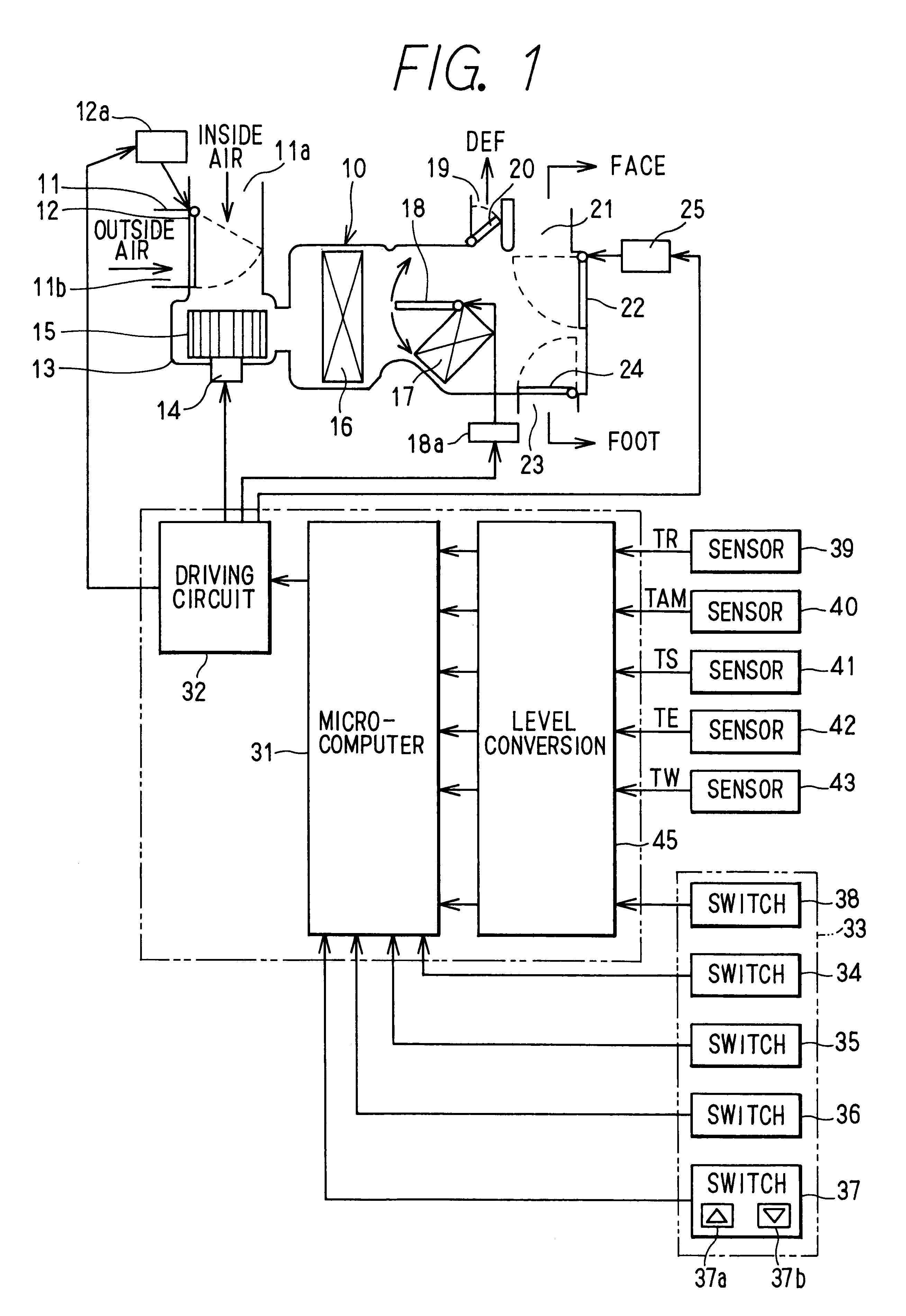
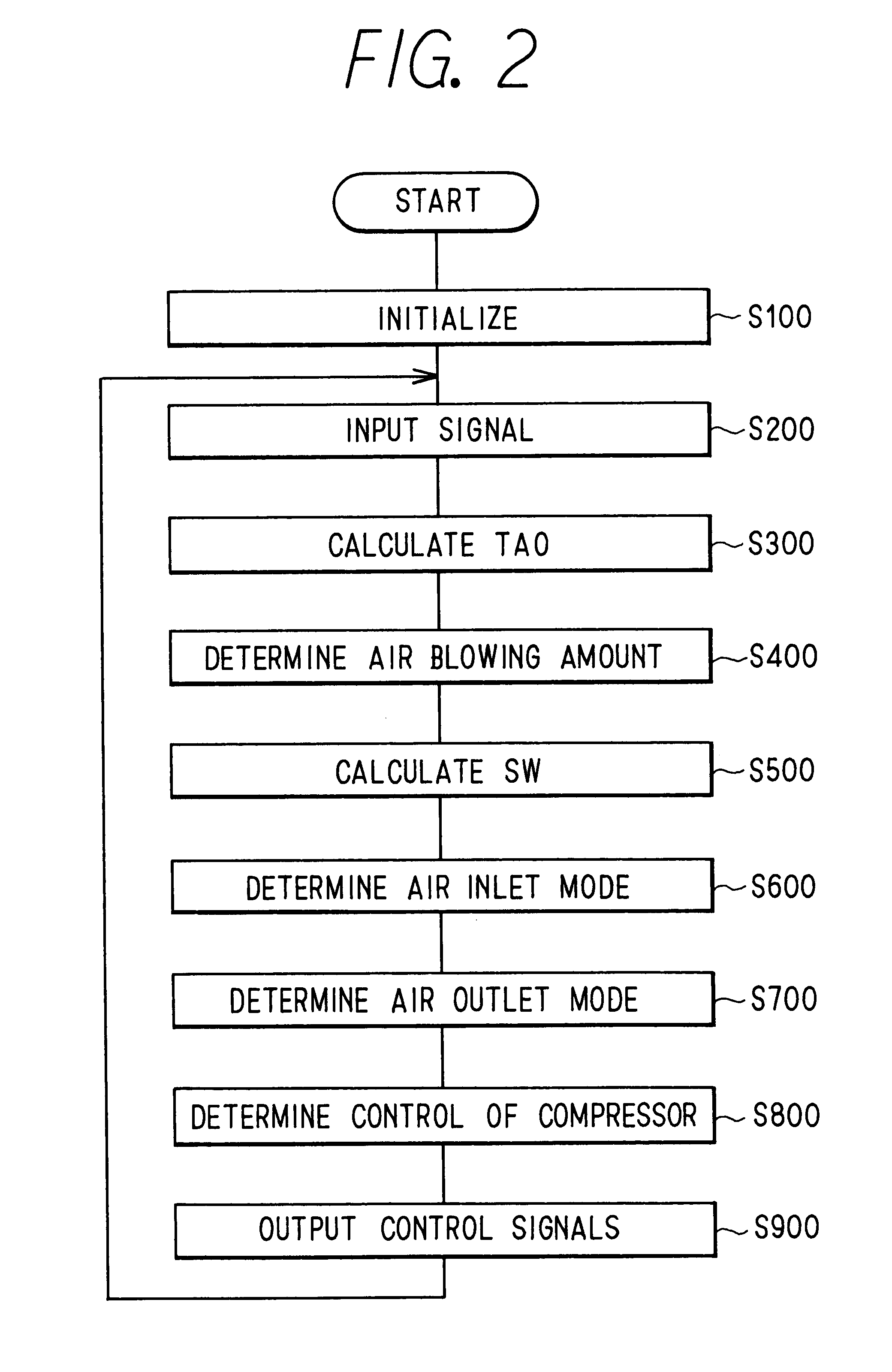
A vehicle air conditioner of FIG. 1 according to the first embodiment automatically controls an air blowing temperature, an air blowing amount, an air inlet mode (air introduction mode), an air outlet mode and the like by automatically controlling air-conditioning control components based on stored control characteristics. Further, the vehicle air conditioner corrects the stored control characteristics for automatic control, based on a passenger's introduction such as manual operation of a passenger. The vehicle air conditioner includes an air conditioning unit 10 used as an interior unit, an inside-outside air switching box 11 used as an air-inlet mode switching device at the most upstream air side of the air conditioning unit 10, and the like. The air conditioning unit 10 is disposed inside a passenger compartment of the vehicle. The switching box 11 includes an outside introduction port 11b, an inside air introduction port 11a and an inside-outside air switching...

second embodiment

(Second Embodiment)

In the above-described first embodiment, it is determined whether or not the passed time after the start of the automatic air-conditioning operation is equal to or shorter than the predetermined time T seconds at step S404 shown in FIG. 3, and the correction method of the control pattern is changed in accordance with the passed time. However, in the second embodiment shown in FIG. 6, the correction method of the control pattern is changed in accordance with the target blowing temperature TAO at the manual operation of the air blowing amount in place of the passed time at step S404 shown in FIG. 3. Specifically, when the target blowing temperature TAO, at the manual operation for reducing the air blowing amount, is equal to or lower than .alpha. or is equal to or higher than .beta. in FIG. 6, the air blowing amount in the large blowing amount area is reduced as shown in FIG. 4A. When the target blowing temperature TAO, at the manual operation for reducing the air b...

third embodiment

(Third Embodiment)

In the above-described second embodiment, the correction method is changed in accordance with the target blowing temperature TAO at the blowing-amount manual operation. However, in the third embodiment shown in FIG. 7, the correction method is changed in accordance with a difference of the target blowing temperature TAO. Here, the difference is between the target blowing temperature TAO at the switching point E, where the air blowing amount is started to be reduced from the large blowing amount area to the intermediate blowing amount area, and the target blowing temperature TAO at the blowing-amount manual operation. Specifically, when the air blowing amount is manually reduced in the low temperature area of the target blowing temperature TAO lower than the switching point E by a temperature difference larger than .gamma., the air blowing amount in the large blowing amount area is reduced as shown in FIG. 4A. When the air blowing amount is manually reduced in the l...


PUM


Abstract

In a vehicle air conditioner, when a passenger manually reduces an air blowing amount in a large blowing amount area of automatic control, a correction of the blower voltage control characteristic is changed in accordance with a condition capable of determining a passenger's request. For example, as the condition, at least one of a target blowing temperature of air blown into a passenger compartment and a passed time after start of the automatic control can be used. Therefore, the corrected blower voltage control characteristic after the manual operation can be made suitable for the passenger's preference.

Description

This application is related to and claims priority from Japanese Patent Application No. 2001-346198 filed on Nov. 12, 2001, the content of which is hereby incorporated by reference.1. Field of the InventionThe present invention relates to a vehicle air conditioner for automatically controlling an amount of air blown into a passenger compartment, which corrects an automatic control characteristic of the air blowing amount based on a manual operation of a passenger. More particularly, the present invention relates to a control method of a control system in the vehicle air conditioner.2. Description of Related ArtIn a vehicle air conditioner disclosed in JP-A-3-54015 or JP-A-7-25221, an air blowing amount corrected based on a manual operation of the passenger is learned, so that an automatic control characteristic of an air blowing amount is fitted to a passenger's preference. In the vehicle air conditioner disclosed in JP-A-3-54015, when an air blowing amount is manually reduced from ...

Claims


Application Information

Patent Timeline
Patent Type & Authority Patents(United States)
IPC IPC(8): B60H1/00F24F11/00
CPCB60H1/00828F24F11/0079Y02B30/746F24F11/77Y02B30/70
Inventor OHGA, AKIRAKAWAI, TAKAYOSHIICHISHI, YOSHINORIKAJINO, YUICHI
Owner DENSO CORP
Learn More