Molding apparatus with mold block section transfer system

a transfer system and mold technology, applied in the field of mold block section transfer system, can solve the problems of dangerous conditions, inefficient time-consuming, and the need to shut down the molding operation, and achieve the effect of reducing the risk of plastic build-up in the extrusion equipment, and avoiding the need for re-operation

Inactive Publication Date: 2003-11-11
LUPKE MANFRED A A +1
View PDF6 Cites 22 Cited by
  • Summary
  • Abstract
  • Description
  • Claims
  • Application Information

AI Technical Summary

Benefits of technology

The present invention provides molding apparatus having a moving mold region in which mold block replacement is carried out without having to interrupt operation of the molding apparatus.

Problems solved by technology

This known method of mold block replacement results in a number of drawbacks.
Firstly, it is time inefficient in that the molding operation must be shut down during the replacement.
Secondly, it can result in hazardous conditions as a result of the shut down.
Specifically, when the shut down occurs, there is a possibility of dangerous plastic build up in the extrusion equipment which must be cleared before the extrusion equipment can be started up again.

Method used


Image

  • Molding apparatus with mold block section transfer system
  • Molding apparatus with mold block section transfer system
  • Molding apparatus with mold block section transfer system

Examples


Embodiment Construction

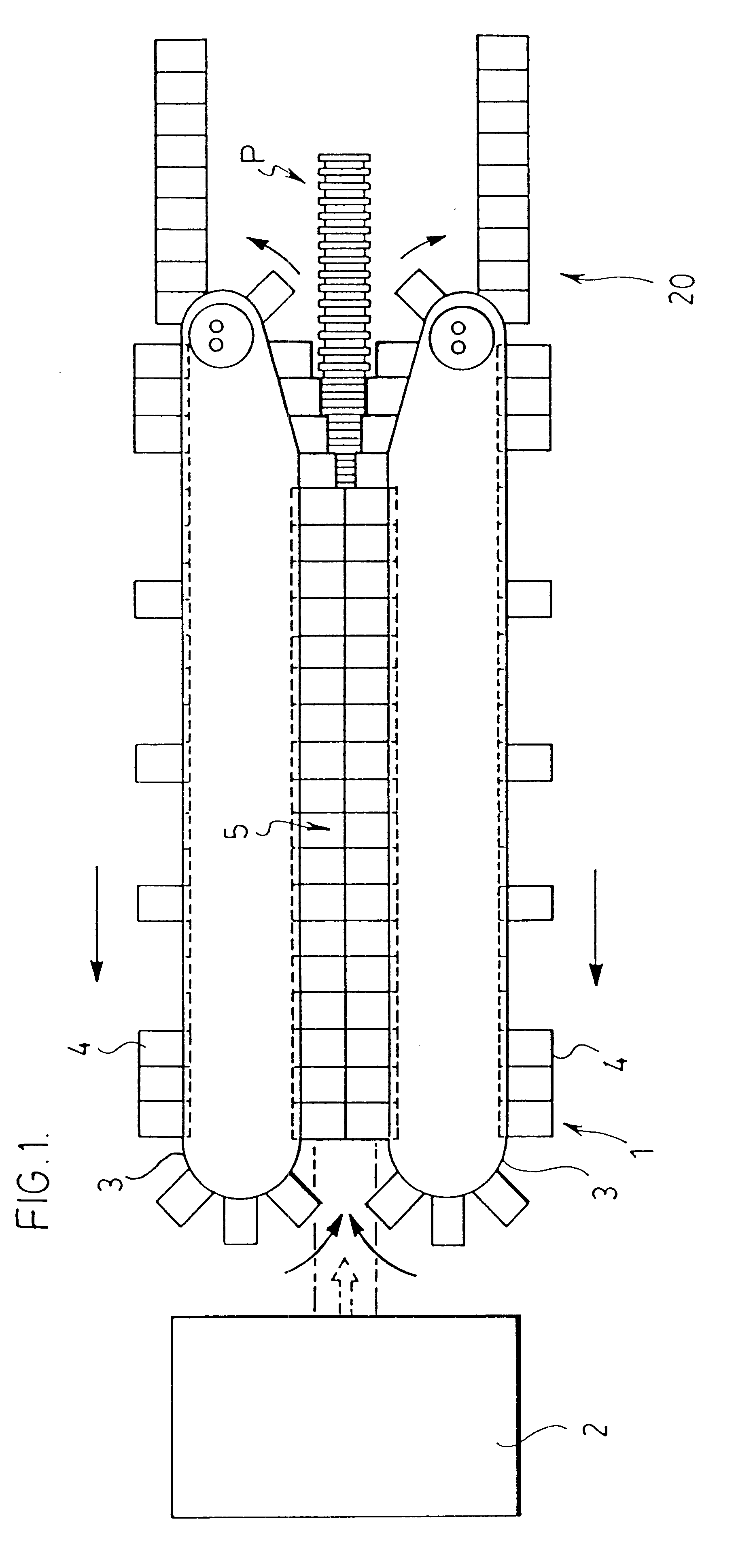
FIG. 1 shows a molding apparatus generally indicated at 1. This molding apparatus comprises a pair of endless tracks 3 with a plurality of mold block sections 4 being carried around each of the tracks. The two tracks have track regions adjacent and parallel one another where the mold block sections from the upper track meet with the mold block sections of the lower track to form a moving mold tunnel 5. An extruder 2 feeds molten plastic into the upstream end of the mold tunnel where a pipe P is formed emerging from the downstream end of the mold tunnel.

As indicated by the arrows in FIG. 1, mold block sections 3 continuously circulate around the two tracks. Each of the tracks include a quick return on the track regions away from the mold tunnel where the mold block sections are separated from one another. This quick return does not form part of the present invention.

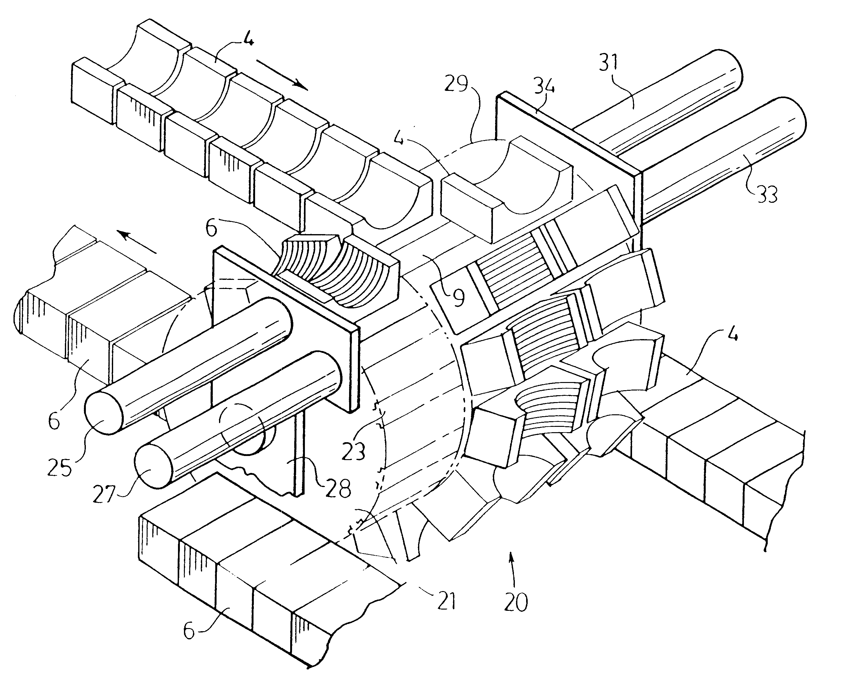
A mold block replacement or transfer system generally indicated at 20 is provided at the downstream end of the molding ...


PUM

PropertyMeasurementUnit
spring pressureaaaaaaaaaa
speedaaaaaaaaaa
timeaaaaaaaaaa

Abstract

A molding apparatus which is used in a continuous molding operation includes an endless looped track, track carriers which are moved around the track to and from a product shaping mold region and a transfer system for replacement of mold block members used in the apparatus. The transfer system, which operates without interrupting the molding operation includes transfer carriers controlled to move synchronized with the track carriers at a transfer location remote from the mold region and actuators which slide the mold block members between the track carriers and the transfer carriers at the transfer location when the transfer carriers are synchronized with the track carriers.

Description

The present invention relates to a system for replacing mold blocks in a moving mold tunnel molding apparatus. According to the present invention, the mold blocks are replaced without interrupting operation of the molding apparatus.Molding apparatus, such as pipe molds, have mold blocks which continuously move around an endless track. On one side of the track the mold blocks are in a closed condition to form a moving mold tunnel where product is shaped within the molding apparatus. The mold blocks open at the downstream end of the tunnel to release the product and are then recirculated back to the upstream end of the mold tunnel.There are currently two different styles of molding apparatus having moving mold tunnels. According to one of these styles which is known as a clam shell type molder, a pair of mold block sections are mounted on a common carrier which circulates around a single looped track. The mold block sections hinge to open and close relative to one another on opposite ...

Claims


Application Information

Patent Timeline
Patent Type & Authority Patents(United States)
IPC IPC(8): B29C33/00B29C33/36B29C49/00B29C47/12B29C48/09B29C48/13B29C48/30
CPCB29C33/36B29C47/126B29C49/0021B29C47/0023B29L2023/18B29C47/0033B29C48/09B29C48/13B29C48/303B29C48/3001B29C48/2528B29C48/2566B29C49/0022B29C49/0027
Inventor LUPKE, MANFRED A. A.LUPKE, STEFAN A.
Owner LUPKE MANFRED A A
Why Eureka
Try Eureka