
VCT lock pin having a tortuous path providing a hydraulic delay

a technology of vct lock pin and tortuous path, which is applied in the direction of valve drives, couplings, machines/engines, etc., can solve the problems of affecting the operation of the valve control system

Inactive Publication Date: 2003-11-18
BORGWARNER INC
View PDF13 Cites 11 Cited by
  • Summary
  • Abstract
  • Description
  • Claims
  • Application Information

AI Technical Summary

Problems solved by technology

Since the phasers cannot be perfectly sealed they are subject to oil loss through leakage.
However, when the engine is shut down, the oil can leak from the VCT mechanism.
During engine start conditions, before the engine oil pump generates oil pressure, the lack of controlling oil pressure may allow the phaser to oscillate excessively due to lack of oil, producing noise and possibly damaging the mechanism.
Due to this restriction, a small delay is introduced in releasing the locking pin and is specifically viewed as a disadvantage by the inventors of U.S. Pat. No. 5,927,239.
The disadvantage of the delay is considered to be offset by the elimination of the rattling noises that emanate from the locking piston.
A drawback of these current locking pins is that they unlock with the initial oil pressurization, prior to the phaser having sufficient oil to operate.

Method used


Image

  • VCT lock pin having a tortuous path providing a hydraulic delay
  • VCT lock pin having a tortuous path providing a hydraulic delay

Examples


Embodiment Construction

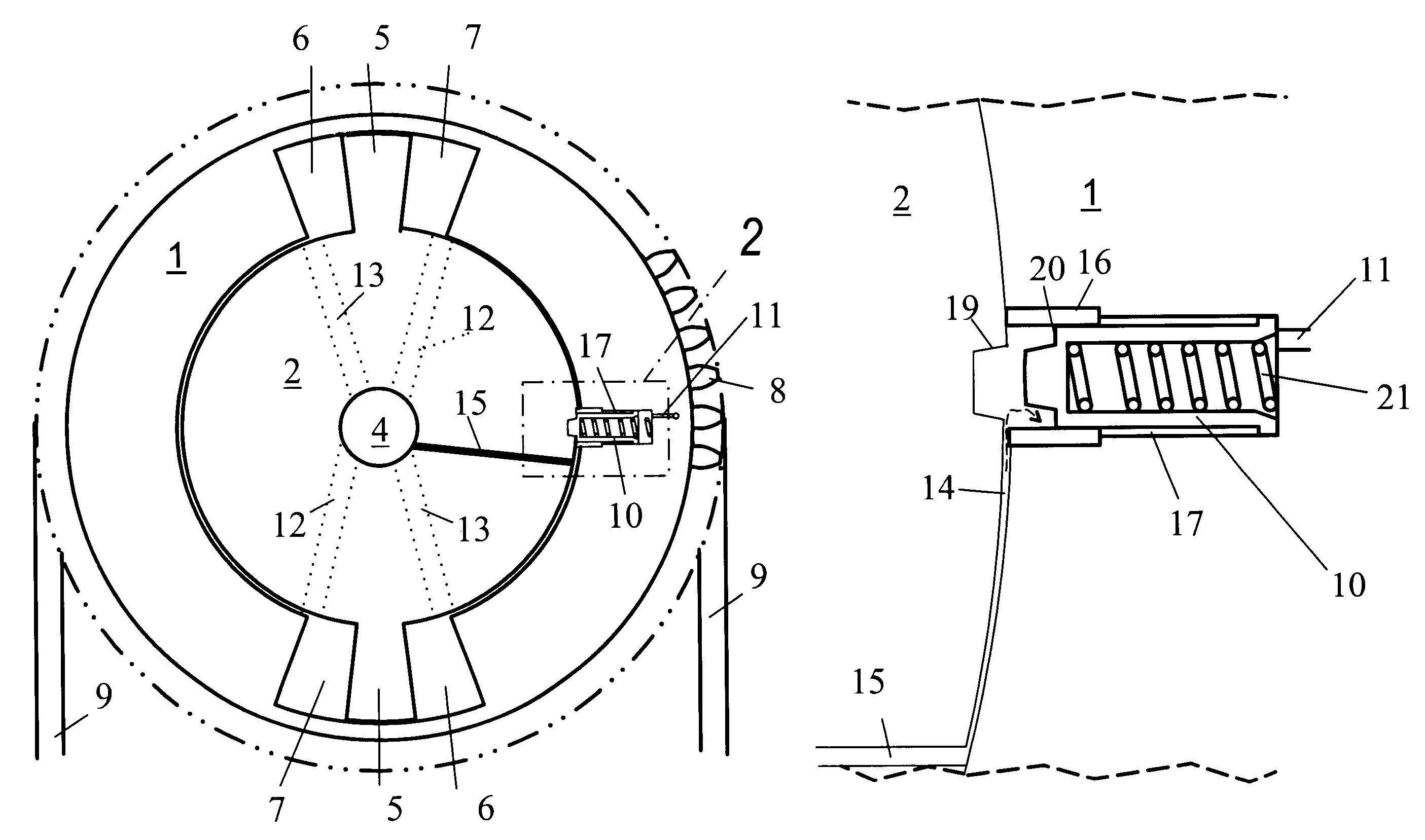
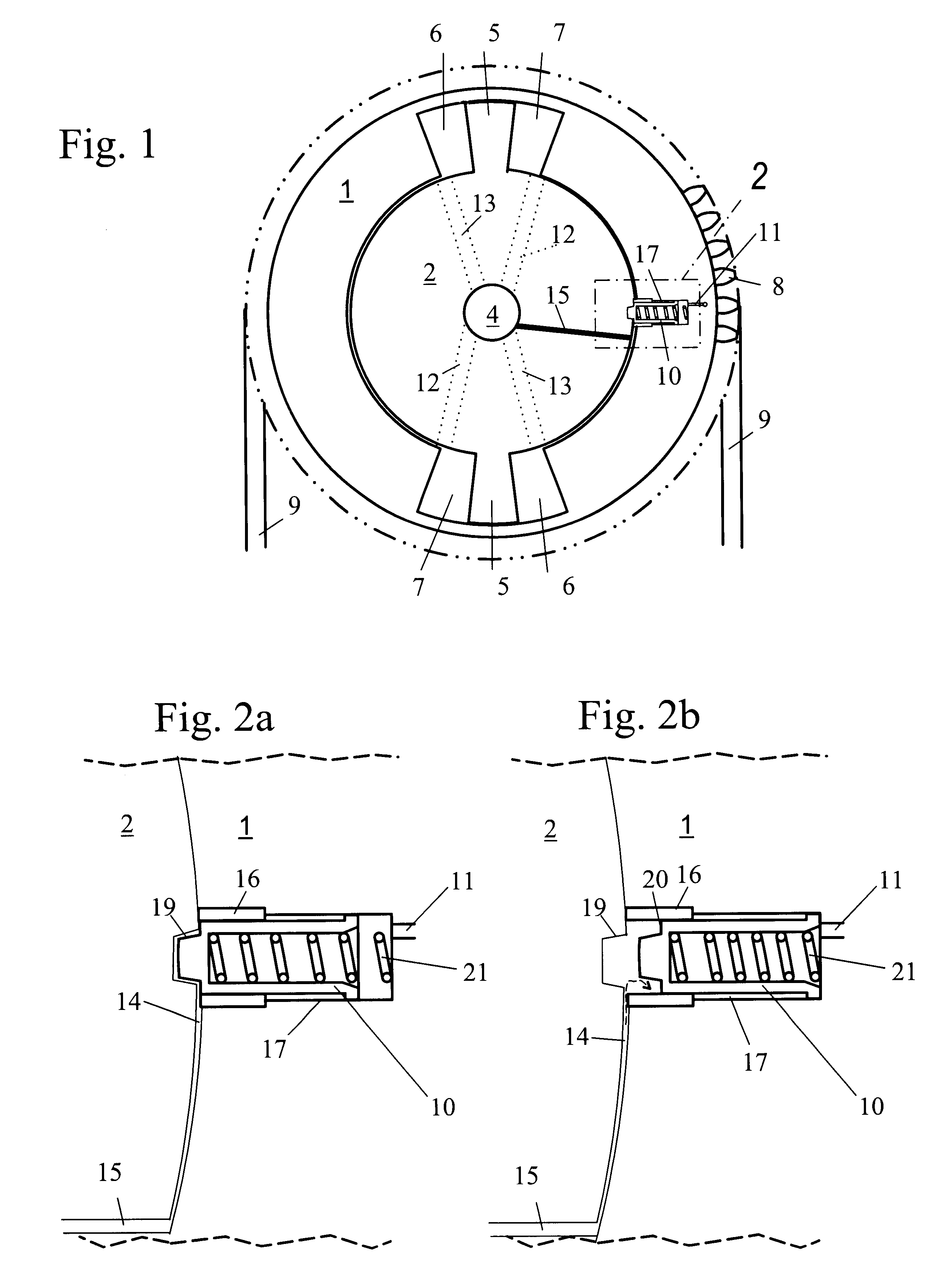
Referring to FIG. 1, a vane-type VCT phaser comprises a housing (1), the outside of which has sprocket teeth (8) which mesh with and are driven by timing chain (9). Inside the housing (1) are fluid chambers (6) and (7). Coaxially within the housing (1), free to rotate relative to the housing, is a rotor (2) with vanes (5) which fit between the chambers (6) and (7), and a central control valve (4) which routes pressurized oil via passages (12) and (13) to chambers (6) and (7), respectively. Pressurized oil introduced by valve (4) into passages (12) will push vanes (5) counterclockwise relative to the housing (1), forcing oil out of chambers (6) into passages (13) and into valve (4).

It will be recognized by one skilled in the art that this description is common to vane phasers in general, and the specific arrangement of vanes, chambers, passages and valves shown in FIG. 1 may be varied within the teachings of the invention. For example, the number of vanes and their location can be ch...


PUM


Abstract

A variable cam timing phaser having a tortuous path from the supply of pressurized oil to the tapered recess into which the locking pin fits, that introduces a delay between when the engine starts and when the locking pin moves to an unlocked position. The tortuous path restricts fluid flow, preventing the locking pin from unlocking during engine start-up with the initial oil pressurization, prior to the variable cam timing phaser having sufficient oil to operate. The delay ensures that the chambers of the variable cam timing phaser have time to fill with operating fluid before the phaser is unlocked.

Description

BACKGROUND OF THE INVENTION1. Field of the InventionThe invention is related to a hydraulic control system for controlling the operation of a variable camshaft timing (VCT) system. More specifically, the present invention relates to a control system, which utilizes a tortuous or restricted path to delay the release of the locking pin.2. Description of Related ArtInternal combustion engines have employed various mechanisms to vary the angle between the camshaft and the crankshaft for improved engine performance or reduced emissions. The majority of these variable camshaft timing (VCT) mechanisms use one or more "vane phasers" on the engine camshaft (or camshafts, in a multiple-camshaft engine). In most cases, the phasers have a rotor with one or more vanes, mounted to the end of the camshaft, surrounded by a housing with the vane chambers into which the vanes fit. It is possible to have the vanes mounted to the rotor, and the chambers in the stator, as well. The housing'outer circumf...

Claims


Application Information

Patent Timeline
Patent Type & Authority Patents(United States)
IPC IPC(8): F01L1/344F01L1/34
CPCF01L1/344F01L1/34F01L1/3442F01L2001/34463F01L2001/34473F01L2250/02F01L2250/04F01L2250/06
Inventor LEWIS, JEFF
Owner BORGWARNER INC
Learn More