
Control method of thermostatic system

a control method and thermostatic technology, applied in the direction of process and machine control, lighting and heating equipment, instruments, etc., can solve the problem of inability to achieve the thermostatic control of the water heater

Inactive Publication Date: 2003-11-18
GUARD SOUND IND CO LTD
View PDF2 Cites 14 Cited by
  • Summary
  • Abstract
  • Description
  • Claims
  • Application Information

AI Technical Summary

Benefits of technology

The primary object of the present invention is to provide a control method of a thermostatic system, wherein two electromagnetic valves of a thermostatic system of a water heater can be controlled to perform the control of gas charge and discharge of a second gas room so as to push a valve sheet forwards or backwards. Thereby, gas outflow of a first gas outlet output to a hot water heater can be exactly controlled so that the linkage with temperature change of the water heater is more apparent. Thermostatic control of the water heater can thus be achieved.
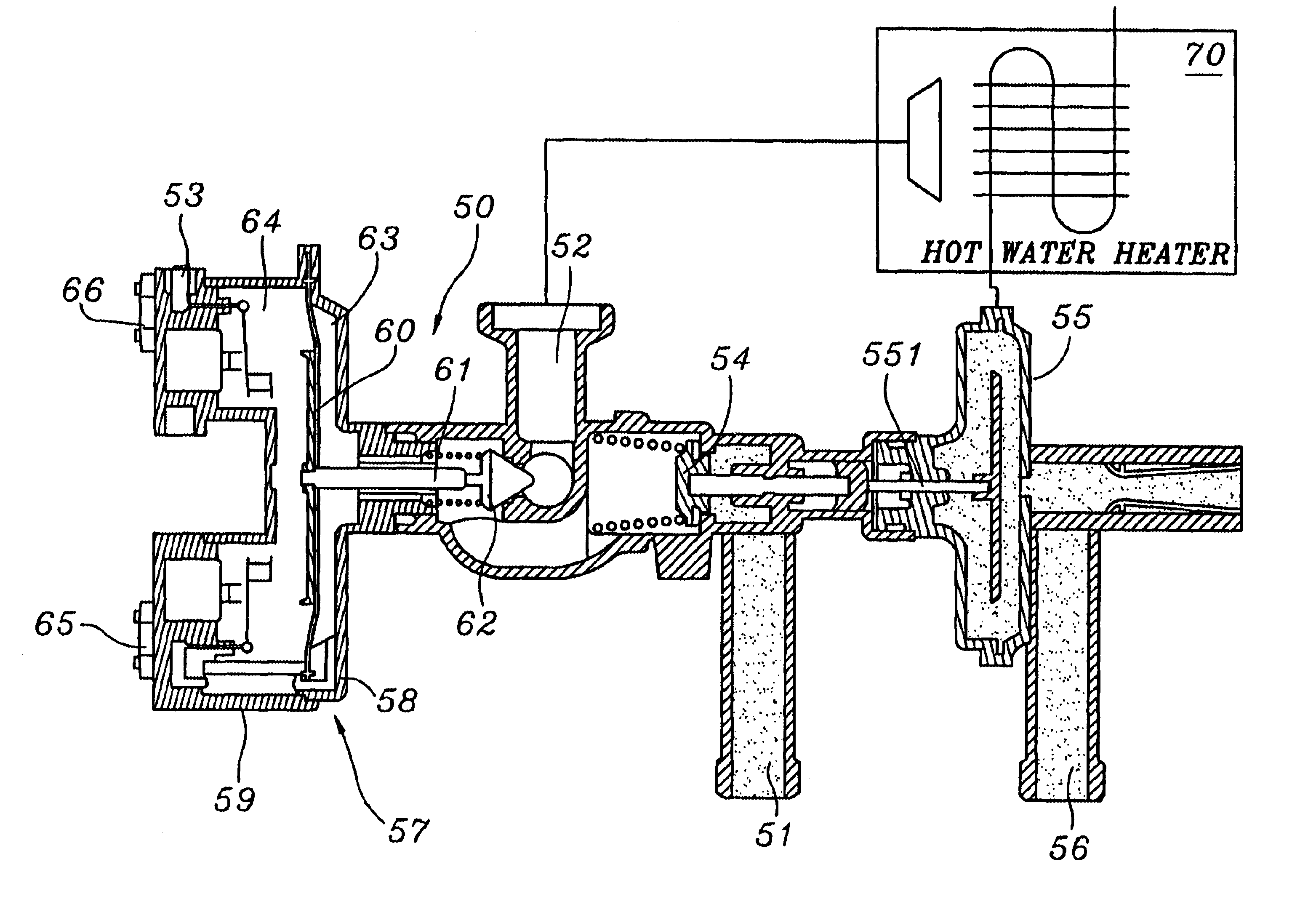
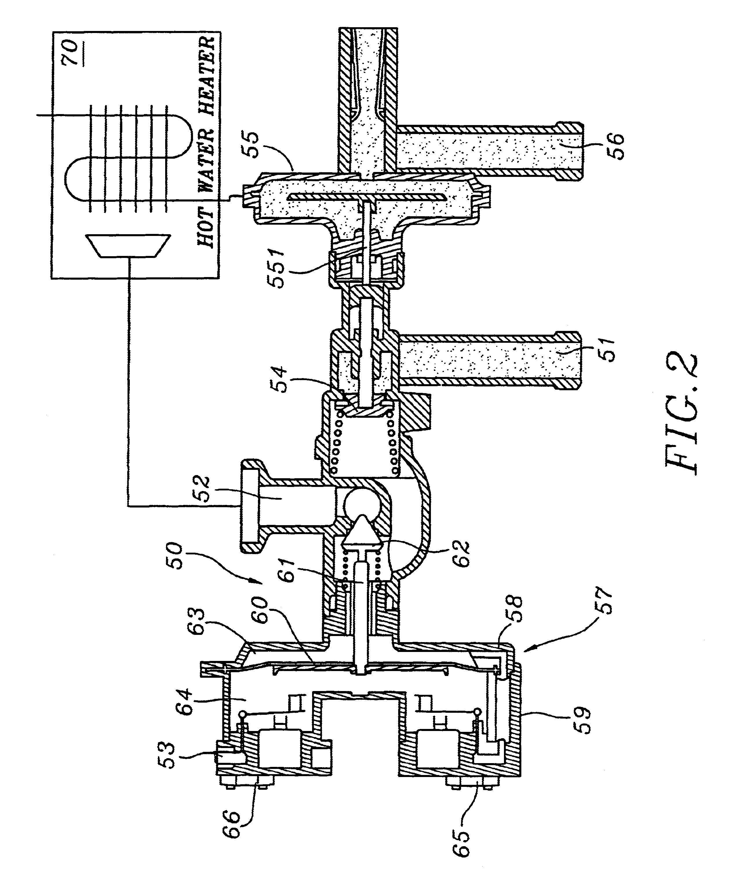
To achieve the above object, the present invention provides a control method of a thermostatic system. When gas outflow output to a main stove is too large, the first electromagnetic valve is controlled to be open and the second electromagnetic valve is controlled to be closed. Gas will be transferred from the first gas room to the second gas room. The control of gas charge of the second gas room is thus performed so as to decrease the open degree of the first gas outlet used to output gas to the hot water heater, hence decreasing gas outflow. When gas outflow output to the hot water heater is too small, the first electromagnetic valve is controlled to be closed and the second electromagnetic valve is controlled to be open. Gas cannot be transferred to the second gas room, and gas in the second gas room can be output via the second gas outlet used to output gas to a pilot flame. The control of gas discharge of the second gas room is thus performed so as to increase the open degree of the first gas outlet, hence increasing gas outflow.

Problems solved by technology

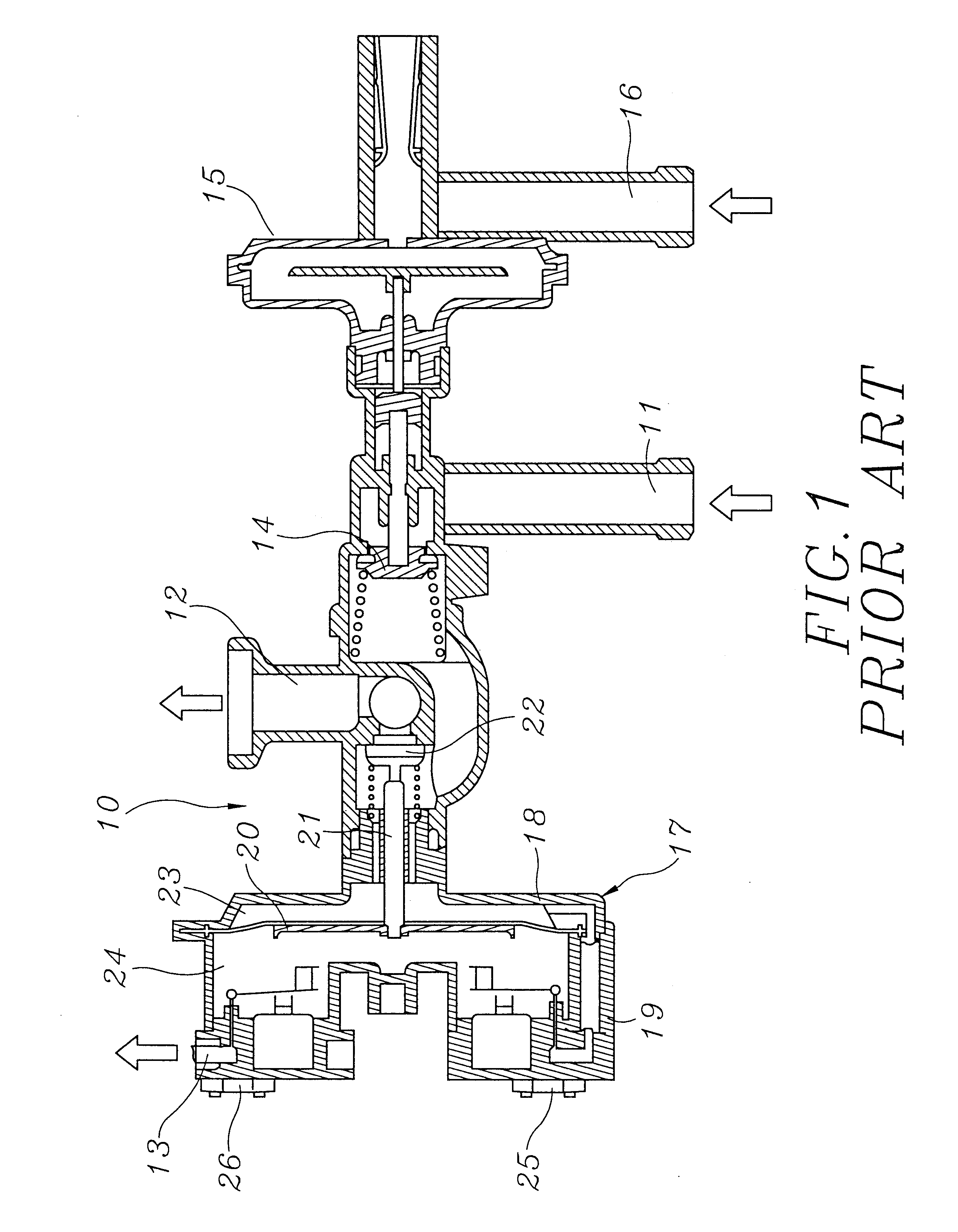
Gas outflow of the first gas outlet 12 output to the main stove can not be exactly controlled so that thermostatic control of the water heater can not be achieved.

Method used


Image

  • Control method of thermostatic system
  • Control method of thermostatic system
  • Control method of thermostatic system

Examples


Embodiment Construction

The present invention relates to a control method of a thermostatic system as shown in FIG. 2. The present invention is applicable to a thermostatic system 50 of a general hot water heater 70. The thermostatic system 50 is roughly like a gas switch control system of prior art. The thermostatic system 50 comprises a gas inlet 51 for inputting gas, a first gas outlet 52 for outputting gas to hot water heater 70, and a second gas outlet 53 for outputting gas to a pilot flame. A valve 54 is arranged between the gas inlet 51 and the first gas outlet 52 and the second gas outlet 53. The action of the valve 54 is controlled by a thimble 551 of a water pan 55. The water pan 55 has a cold water inlet 56. When cold water is input from the cold water inlet 56 into the water pan 55, the thimble 551 will be jointly moved so that the valve 54 will be pushed open to let gas be transferred from the gas inlet 51 to the first gas outlet 52 and the second gas outlet 53.

A switch middle seat 57 is insta...


PUM


Abstract

A control method of a thermostatic system for a hot water heater is provided where when the water temperature in the hot water heater is too large, a first electromagnetic valve is controlled to be open and a second electromagnetic valve is controlled to be closed. Gas will be transferred via the first gas room to the second gas room. The control of the electromagnetic valves causes a decrease in gas outflow to the hot water heater. When the water temperature in the hot water heater is too small, the first electromagnetic valve is controlled to be closed and the second electromagnetic valve is controlled to be open. The further control of the electromagnet valves causes an increase in the open degree of a gas outlet valve, hence increasing gas outflow.

Description

The present invention relates to a control method of a thermostatic system and, more particularly, to a control method applicable to a water heater, wherein two electromagnetic valves are exploited to exactly control gas outflow at the gas outlet. Thereby, thermostatic control of the water heater can be achieved.As shown in FIG. 1, a gas switch control system 10 is installed in a prior art water heater. The gas switch control system 10 comprises a gas inlet 11 for inputting gas, a first gas outlet 12 for outputting gas to a main stove, and a second gas outlet 13 for outputting gas to a pilot flame. A valve 14 is arranged between the gas inlet 11 and the first gas outlet 12 and the second gas outlet 13. The action of the valve 14 is controlled by a water pan 15. When cold water is input from a cold water inlet 16 into the water pan 15, the valve 14 will be pushed open so that gas can be transferred from the gas inlet 11 to the first gas outlet 12 and the second gas outlet 13.A switch...

Claims


Application Information

Patent Timeline
Patent Type & Authority Patents(United States)
IPC IPC(8): F23N1/08
CPCF23N1/085F23N2035/24F23N2035/18F23N2035/14F23N2235/18F23N2235/14F23N2235/24
Inventor CHAN, NIEN-FENG
Owner GUARD SOUND IND CO LTD
Learn More