Sanitary device

a technology of sanitary devices and sanitary pads, which is applied in the direction of lavatory sanitory, bathroom covers, physical therapy, etc., can solve the problems of the most troublesome operation of manual adjusting in the entire manufacturing process, and achieve the effect of facilitating the adjusting work

Inactive Publication Date: 2003-11-18
AISIN SEIKI KK
View PDF6 Cites 10 Cited by
  • Summary
  • Abstract
  • Description
  • Claims
  • Application Information

AI Technical Summary

Benefits of technology

to provide a sanitary device which can facilitate the adjusting work for presetting the temperature in accordance with the individual preference or the weather conditions of a specified area.

Problems solved by technology

This manual adjusting operation is one of the most troublesome operations in the entire manufacturing process.

Method used


Image

  • Sanitary device
  • Sanitary device
  • Sanitary device

Examples


Embodiment Construction

The embodiments of the invention will be explained with the reference to the attached drawings.

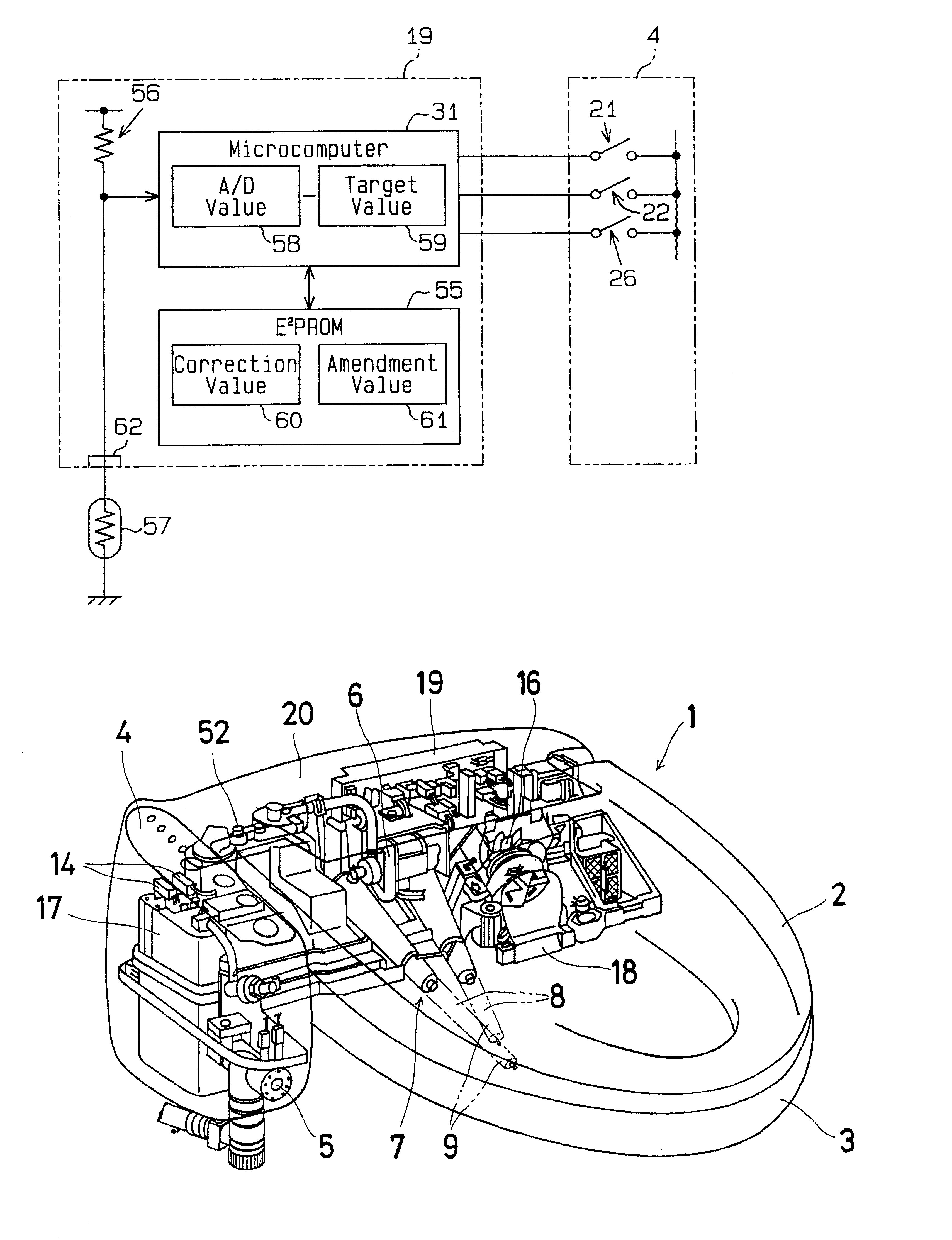
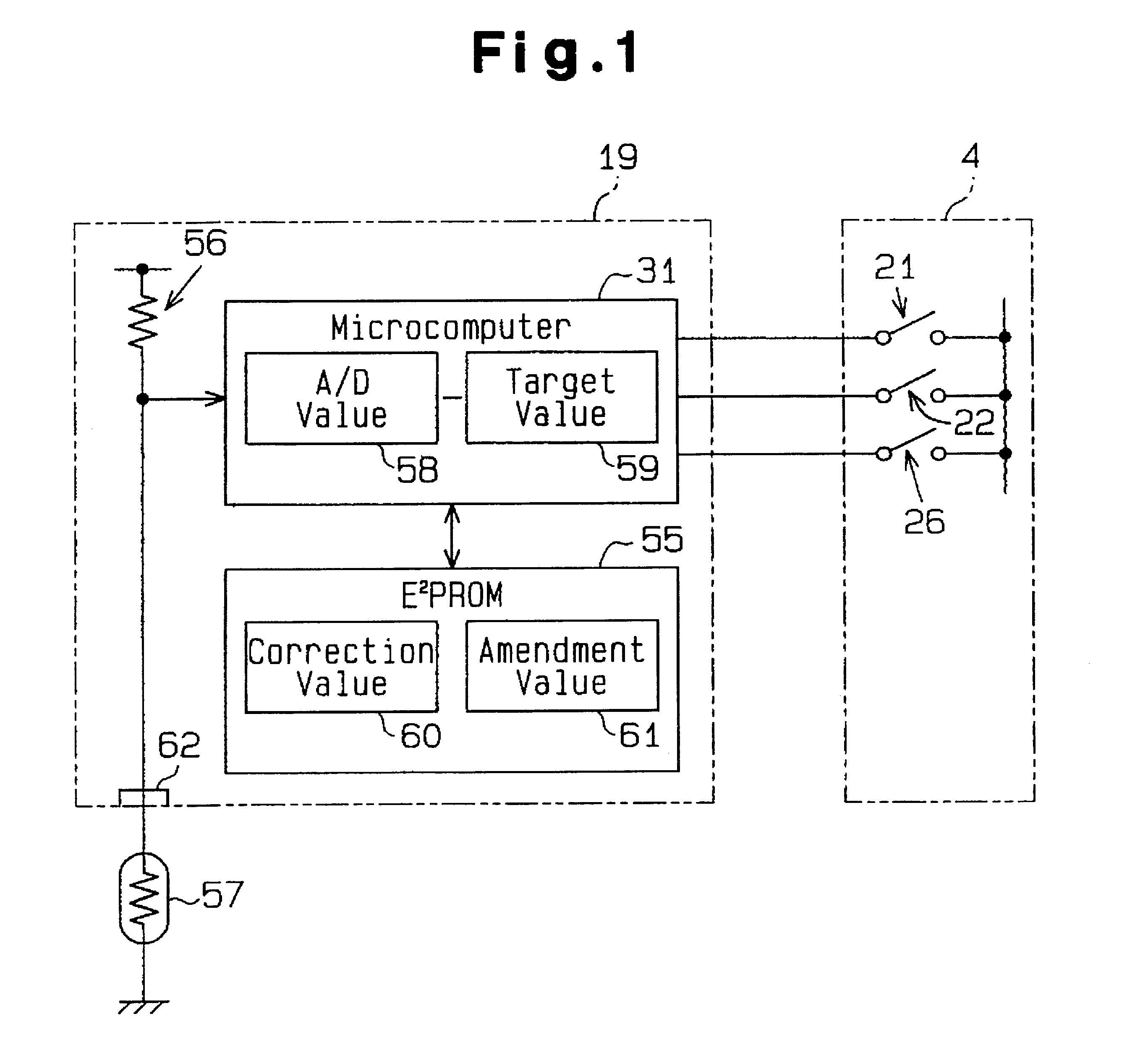
The sanitary device of the present invention shown in FIG. 1 includes an E.sup.2 PROM 55 (corresponding to the non-volatile memory) on the control substrate 19 in addition to the conventional sanitary device in FIG. 5 and omits the variable resistor 101 of the control substrate 19. The sanitary device 1 according to the present invention prevents the control difference in the circuit constant of the control substrate 19, requiring an adjustment operation upon the assembly process of the control substrate, according to the flow chart shown in FIG. 2.

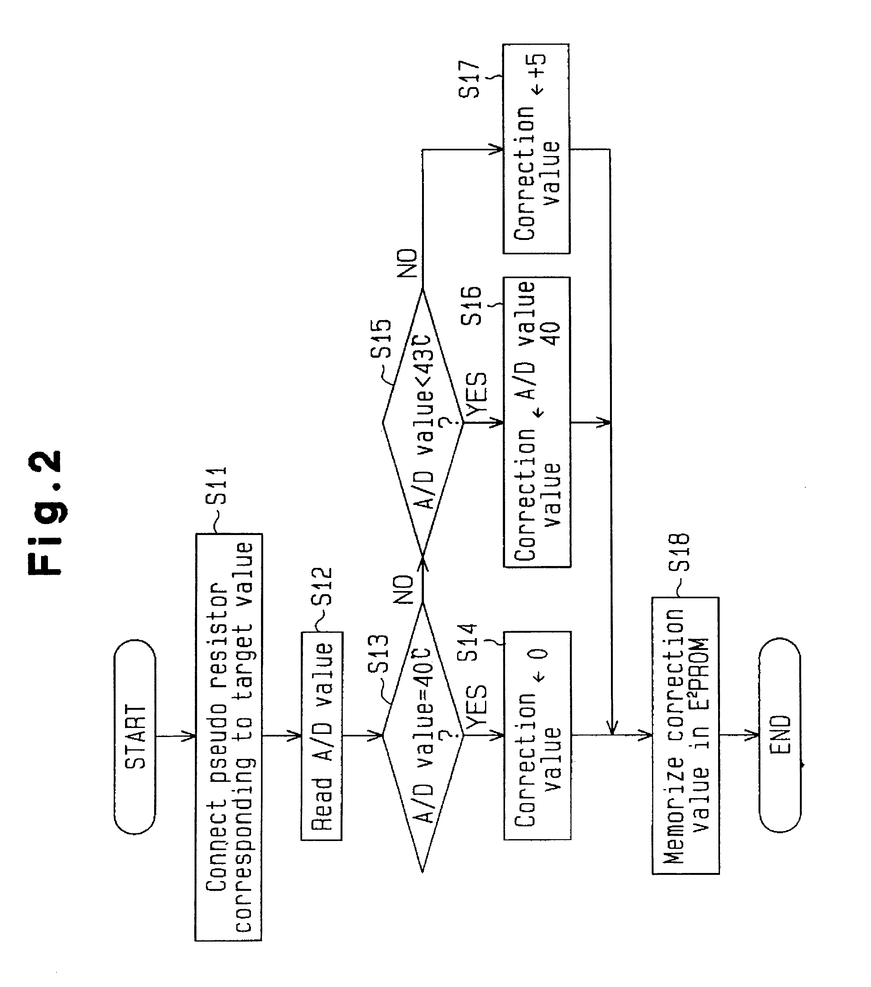
Explaining now the temperature control of the cleansing water in the heating water tank 17 with reference to FIG. 2, first, at step S11 the pseudo resistor 57 corresponding to the target value 59 ("intermediate" temperature on the display LED 51 on the operation panel 4: 40.degree. C.) is connected to the connecting connector of the control subs...


PUM


Abstract

A sanitary device includes a microcomputer for controlling a temperature of a cleansing water in a heating water tank to a target value, a control substrate installing the microcomputer and a non-volatile memory memorizing a correction value for the target value. The microcomputer corrects the correction value based on the variation of a circuit constant of the control substrate. The microcomputer of the sanitary device further controls a temperature of a toilet seat or a temperature of a drying air to each target value.

Description

The present application is based on and claims priority under 35 U.S.C .sctn.119 with respect to Japanese Patent Application No. 2001-081330 filed on Mar. 21, 2000 (13th Year of Heisei), the entire content of which is incorporated herein by reference.1. Field of the InventionThis invention relates to a sanitary device which controls temperatures of cleansing water, drying air or a toilet seat.2. Description of the Related ArtGenerally, a sanitary device 1 as shown in FIGS. 5-8 controls the temperature of cleansing water for cleansing human private parts such as anus or pubic parts, and drying air for drying such parts after cleansing, or the toilet seat. The sanitary device 1 according to FIG. 5 includes an operation panel 4, a cleansing nozzle 7, a heater 14 for heating the water, a drying air control unit 16 and control substrate 19. The operation panel 4 includes a heating water switch 21 for the heater control, a toilet seat switch 22, a drying air switch 23, a bidet cleansing s...

Claims


Application Information

Patent Timeline
Patent Type & Authority Patents(United States)
IPC IPC(8): E03D9/08A47K13/30
CPCE03D9/08
Inventor NONOMURA, MITSUGU
Owner AISIN SEIKI KK
Why Eureka
Try Eureka