Device for measuring the concentration of gaseous and vaporous components of a gas mixture

Inactive Publication Date: 2003-11-25
DRAGERWERK AG
View PDF5 Cites 11 Cited by
  • Summary
  • Abstract
  • Description
  • Claims
  • Application Information

AI Technical Summary

Benefits of technology

The primary object of the present invention is to improve a device of the class described such that multi-channel arrangements connected in parallel in terms of flow can also be analyzed in a simple manner with an optoelectronic scanning device that evaluates single channels along a scanning section.
The advantage of the present invention is essentially the fact that due to the channels being arranged at an angle to the detection section, the channels can be simultaneously evaluated within the covered area with a scanning section, and so-called spot measurements (which are performed to determine whether or not a certain component or certain components is / are present in the gas sample) can thus be performed in a particularly simple manner. The channels are arranged in the covered area of the scanning section such that they are always in the active area of the scanning section. If the scanning section consists of, e.g., 6 LEDs for scanning the change in the color of the reaction zones, six channels crossing the scanning section can also be evaluated if these are arranged within the range of action of one LED. The channels can be etched or milled into the support, or they may be designed as a film pack with individual channels or as capillary tubes, in which case, e.g., the capillary tubes are placed into the support. The advantage of a simultaneous evaluation of a plurality of channels for the user is the fact that information on the type of the composition of the gas sample to be investigated can be obtained by a single measurement after a short measurement time, without the support having to be moved within the detection device. Once the substance being sought is identified, the substance can subsequently be quantitatively analyzed by a one-channel measurement, i.e., with a channel extending along the scanning section.

Problems solved by technology

This increases the time needed for the evaluation.
Even though it would be possible to simultaneously evaluate even more channels by installing additional LEDs, which are arranged in a matrix-like pattern, this would lead to a disproportionate increase in the price of the optoelectronic scanning device, especially because the additional LEDs are not needed during the evaluation of a single channel.
Flow of the component to be detected through individual capsules from a gas inlet to a gas outlet is not provided and is also not possible, because the detection substance occurs as a liquid, which completely fills the capsule.

Method used


Image

  • Device for measuring the concentration of gaseous and vaporous components of a gas mixture
  • Device for measuring the concentration of gaseous and vaporous components of a gas mixture
  • Device for measuring the concentration of gaseous and vaporous components of a gas mixture

Examples


Embodiment Construction

. 1.

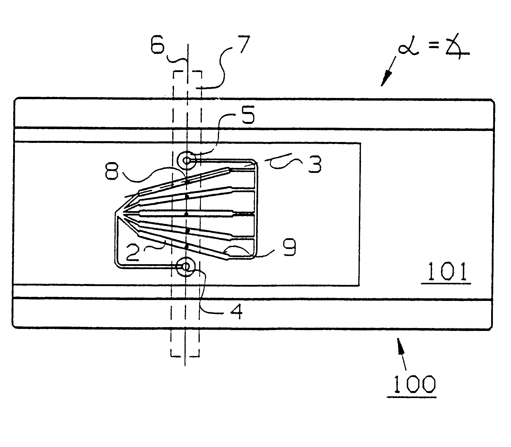
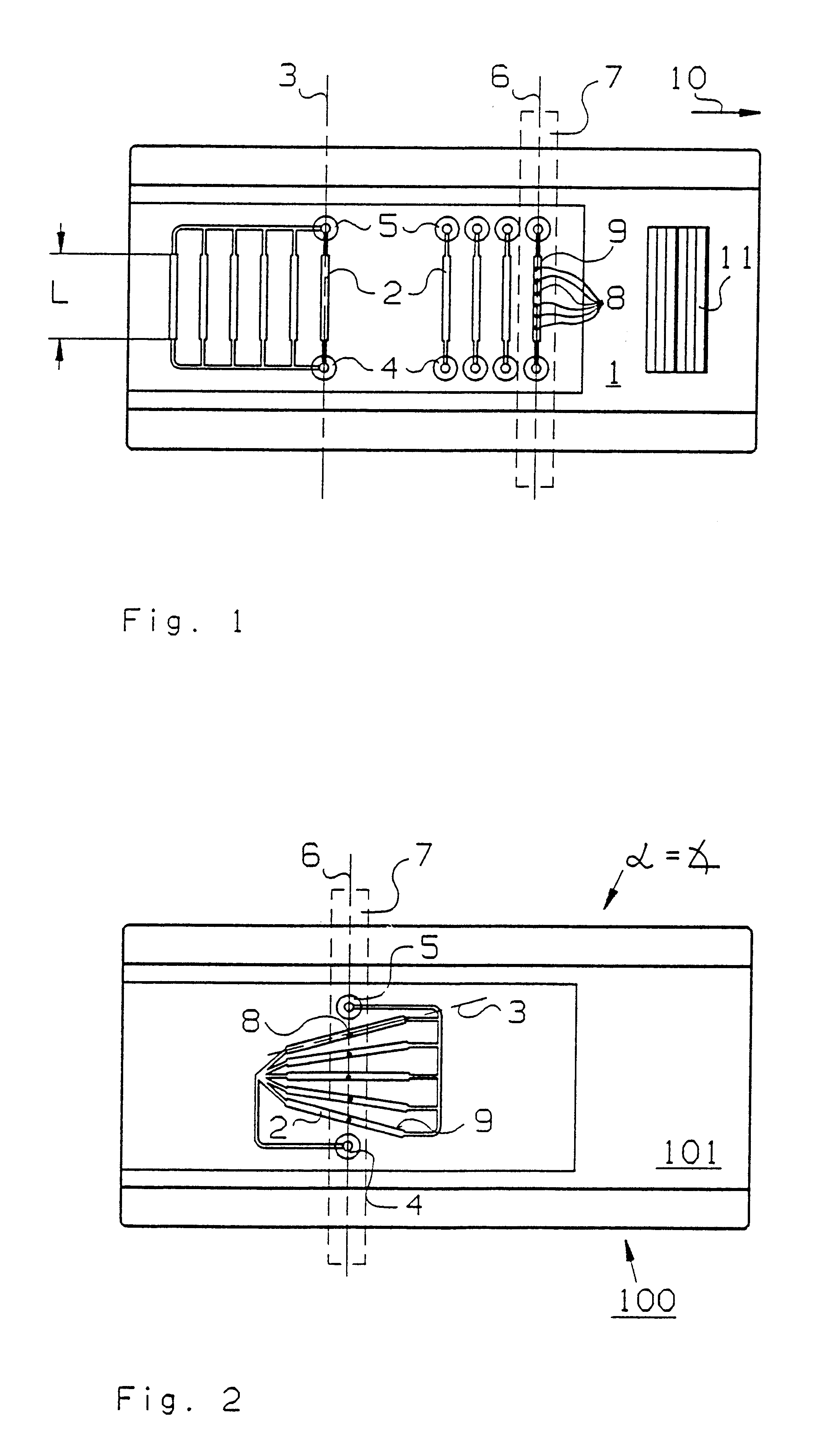
FIG. 1 shows a plate-like, chip-like support 1 with a multiple arrangement of channels 2 according to the state of the art, through which gas flows along a flow axis 3 from a gas inlet 4 to a gas outlet 5. For the sake of greater clarity, FIG. 1 shows only one flow axis 3. The channels 2 have reaction zones 9, which extend within the channels 2 along the flow axis 3 and whose color changes under the action of the component to be detected. The change in color is detected with an optoelectronic scanning device 7, which is illustrated in FIG. 1 only schematically by a dotted line. The individual channels 2 in the embodiment shown are to be brought one after another into the range of action of the optoelectronic scanning device 7, whose optical part consists essentially of an LED array 8 extending along a scanning section 6. The LED array 8 is illustrated in FIG. 1 in the form of 6 discrete points, which represent an LED each, and by means of which the change in color of the reactio...


PUM


Abstract

A device for detecting gaseous and vaporous components of a gas mixture by means of channels 2, which are located next to each other on a support 201, are connected in parallel in terms of flow, and are exposed to the component to be detected along a flow axis 3. A scanning section 6 of a scanning device is provided which extends along one of the channels 2, for detecting the change in color of reaction zones in the channels 2. Multiple channel arrangements can also be analyzed in a simple manner with a scanning section evaluating individual channels. At least some of the channels 2 on the support 201 are directed such that an angle alpha not equal to 0 is formed between the flow axis 3 and the scanning section 6, and the channels 2 are located in the covered area of the scanning section 6.

Description

The present invention pertains to a device for detecting gaseous and vaporous components of a gas mixture by using optically perceptible reaction zones in channels which are located next to one another on a support, are connected in parallel, are arranged between a gas inlet and a gas outlet, and are exposed to the component to be detected along a flow axis following the course of the channel, and with a scanning section of a scanning device, which scanning section extends along at least one of the channels.A device of the above-described type has become known from DE-C39,02,402. In the prior-art device, channels extending in parallel on a chip-like support are provided, wherein gas can flow through the channels from a gas inlet to a gas outlet, and on the inside, which acts as a reaction zone, the channels contain a substance which reacts with the component to be detected. The gas flows through the channels along a flow axis that follows the course of the channel and covers the gas...

Claims


Application Information

Patent Timeline
IPC IPC(8): G01N21/78G01N21/77
CPCG01N21/783
Inventor POOCH, INGOKANEBLEI, INGO
Owner DRAGERWERK AG
Why Eureka
Try Eureka