
Quick hitch attachment

a technology for prime mover and attachment, which is applied in the direction of lifting devices, mechanical machines/dredgers, applications, etc., can solve the problems of increasing the amount of time it takes to either connect or disconnect the attachment from the actuator arm of the excavator, increasing the maintenance cost, etc., to facilitate the connection of the strut, speed up the connection, and reduce the amount of time required

Inactive Publication Date: 2003-12-02
WARD PETER JOHN
View PDF38 Cites 42 Cited by
  • Summary
  • Abstract
  • Description
  • Claims
  • Application Information

AI Technical Summary

Benefits of technology

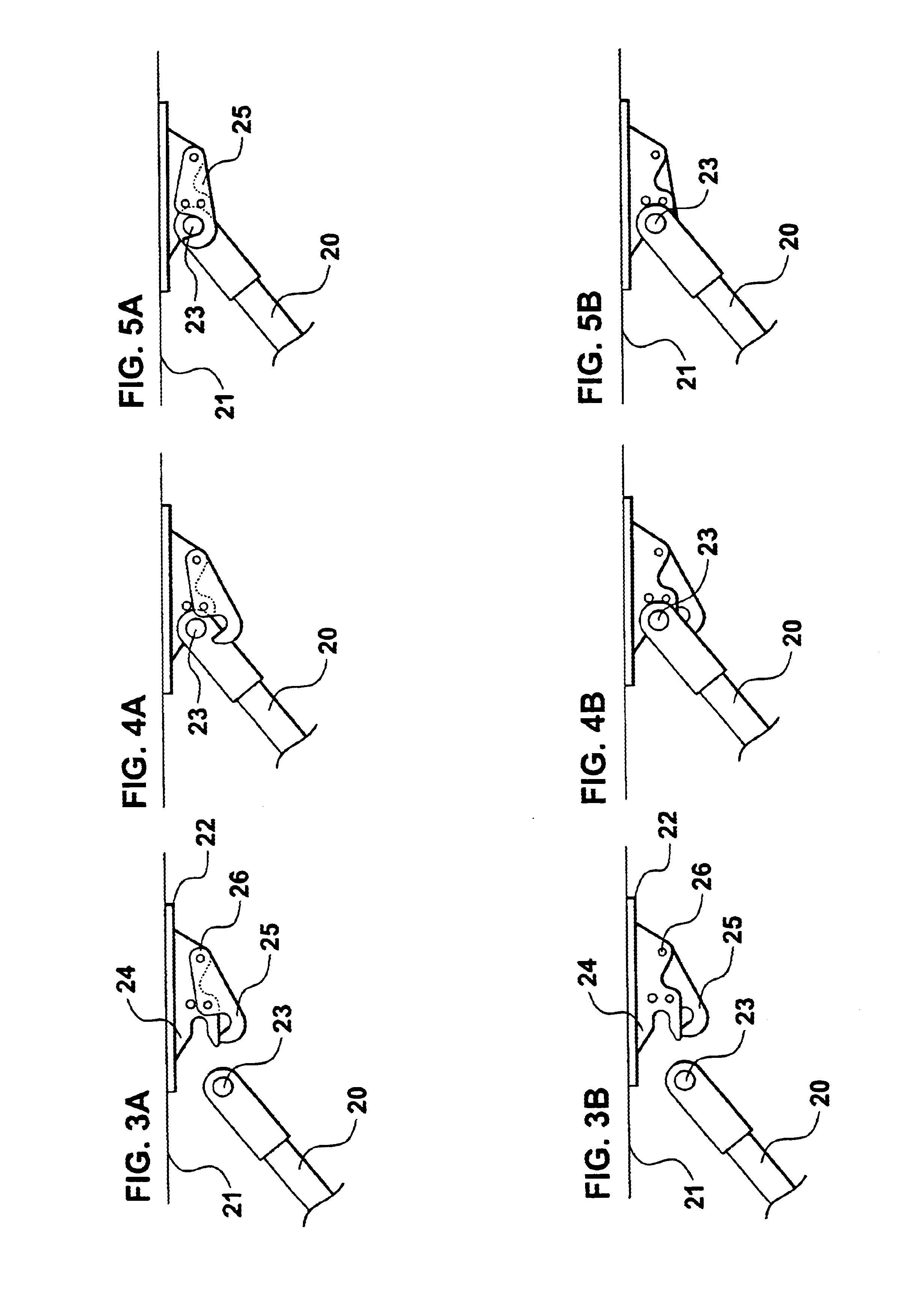
Furthermore, the use of an attachment system substantially as discussed above allows a strut permanently attached to the free jaw to be quickly located and locked in place on the excavator. The excavator's operator simply needs to actuate and move the excavator's ram to slide the free end of the strut in place within the attachment system to lock same in place.
The arrangement and configuration of the attachment discussed above allows it to be combined with quickhitch attachment systems. The mechanical arrangement of the pivot points, levering arms and jaws involved substantially increases the forces applied to close the jaws when a quickhitch is present. As the pivot points for the head and driven connector are further displaced away from the main pivot of the jaws, this substantially increases the levering force applied through these connectors onto any object to be crushed, cut or grasped by the jaws. Through the addition of a quickhitch the attachment may work quickly to cut through dense and strong materials which could cause difficulties to other forms of attachment with lower forces applied to close the attachment jaws.

Problems solved by technology

Therefore these devices also require connections to sources of hydraulic fluid or pressurised gas that increases maintenance costs and increases the time required to connect an attachment to an excavator.
However, one existing problem with this and similar devices is the amount of time it takes to either connect or disconnect the attachment from the excavator's actuator arm.
The separate connection of each of these points to the attachment jaws and the weight of the attachment jaws themselves significantly complicate the connection or disconnection of the attachment to the excavator.

Method used


Image

  • Quick hitch attachment
  • Quick hitch attachment
  • Quick hitch attachment

Examples


Embodiment Construction

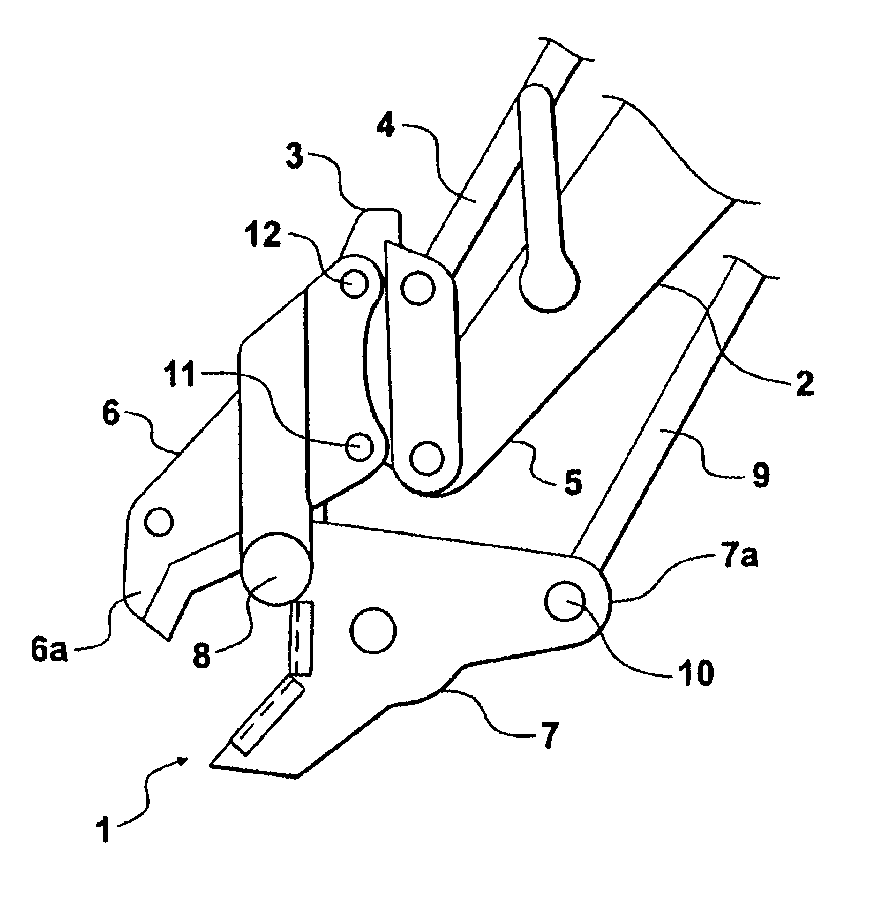
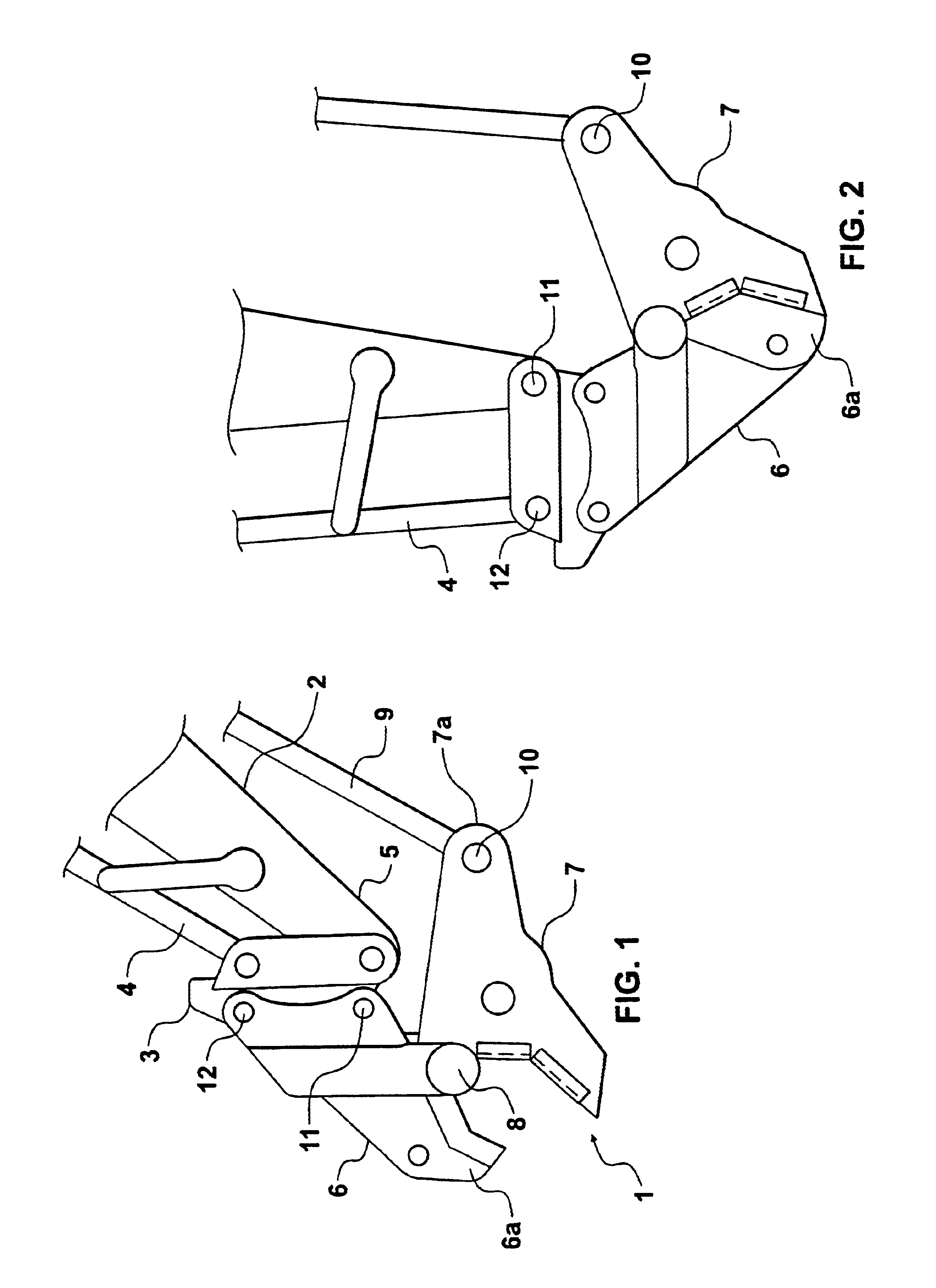
FIG. 1 shows an attachment 1 for an actuator arm 2 of an excavator (not fully shown).

The attachment 1 is indirectly connected to the actuator arm 2 through a quick hitch 3. The quick hitch 3 is directly connected to the actuator arm driven beam 4 and also to the actuator arm head 5. The driven beam 4 is connected to a hydraulic ram (not shown) that is powered or driven by the excavator. In the situation shown in FIG. 1 the excavator ram is retracted. This means that there is no requirement for hydraulic or pneumatic lines to be fitted to the attachment 1 as it may be operated using the excavator's own hydraulic ram and driven beam 4.

The attachment 1 as configured in the embodiment shown is a pair of jaws comprising a first or fixed jaw 6 and a second or free jaw 7. The fixed jaw 6 is pivotally connected to the free jaw 7 by a pivot point 8. The top end 7a of the free jaw is directly connected to the actuator arm strut 9. This strut is connected at its opposite end to the head portio...


PUM

PropertyMeasurementUnit
Distanceaaaaaaaaaa

Abstract

An attachment for a prime mover or backhoe which may be used to cut or crush material. The attachment includes a first jaw, being a fixed jaw, and a second jaw being a free jaw which is pivotably connected to the fixed jaw, and at least three connectors which allow the attachment to be connected to the actuator arm of a prime mover or backhoe. These connectors include a head connector adapted to provide a connection to the head of the actuator arm, and a driven connector adapted to provide a connection to the driving beam of the backhoes actuator arm, and a strut connector adapted to provide a connection to the strut of the backhoes actuator. The head and driven connectors are associated with the fixed jaw and the strut connector is associated with the free jaw, where the head and driven connectors are connected to the prime mover or backhoe with a quickhitch. The arrangement is such that when in use the distance between the driven and head connectors remains constant and the distance between the driven and strut or head and strut connectors varies.

Description

This invention relates to devices used to cut and pulverise materials. Specifically the present invention may be used in the demolition trade to provide a jaw attachment for an excavator and may be configured to be easily and quickly removed from or attached to an excavator. The present invention may also be adapted to engage with a quickhitch located between elements of the excavator and the jaw, where the inclusion of a quickhitch improves the efficiency and the cutting or cutting strength of the attachment.Reference throughout this specification will also be made to the present invention being configured to provide a cutting or pulverising jaw attachment for an excavator used in demolition work. However, it should be appreciated by those skilled in the art that other applications are envisioned for the present invention and reference to the above only throughout this specification should in no way be seen as limiting.A number of cutting, crushing or manipulating jaws have previou...

Claims


Application Information

Patent Timeline
IPC IPC(8): A01G23/087A01G23/00B23D17/00E02F3/04E02F3/96E04G23/08
CPCA01G23/087B23D17/00E04G23/08E02F3/965Y10S414/125E04G23/082
Inventor WARD, PETER JOHN
Owner WARD PETER JOHN
Learn More