Clip fastening system for walls

a technology of fastening system and wall, which is applied in the direction of structural elements, building components, roof coverings, etc., can solve the problems of tedious and time-consuming screwing or riveting of wall sheets, and many customers do not have rivet guns readily availabl

Inactive Publication Date: 2003-12-02
SPANBILT AUSTRALIA
View PDF18 Cites 46 Cited by
  • Summary
  • Abstract
  • Description
  • Claims
  • Application Information

AI Technical Summary

Benefits of technology

Apertures are provided adjacent an associated edge of the side wall at locations corresponding to the detents on the clip-like fitting. When the edge portion of the side wall is inserted between the frame member and the clip-like fitting, the detents locate in the apertures, and prevent the side wall from being pulled out of engagement with the frame member. Hence, a side wall can be manually fastened to a frame element in a simple "push lock" manoeuvre.
In another embodiment, each clip-like fitting is formed integrally with the channel-shaped frame member by pressing a flap outwardly from a side wall of the frame member, and forming an inwardly directed detent on the flap. When a

Problems solved by technology

The screwing or riveting of wall sheets is tedious and time consuming.

Method used


Image

  • Clip fastening system for walls
  • Clip fastening system for walls
  • Clip fastening system for walls

Examples


Embodiment Construction

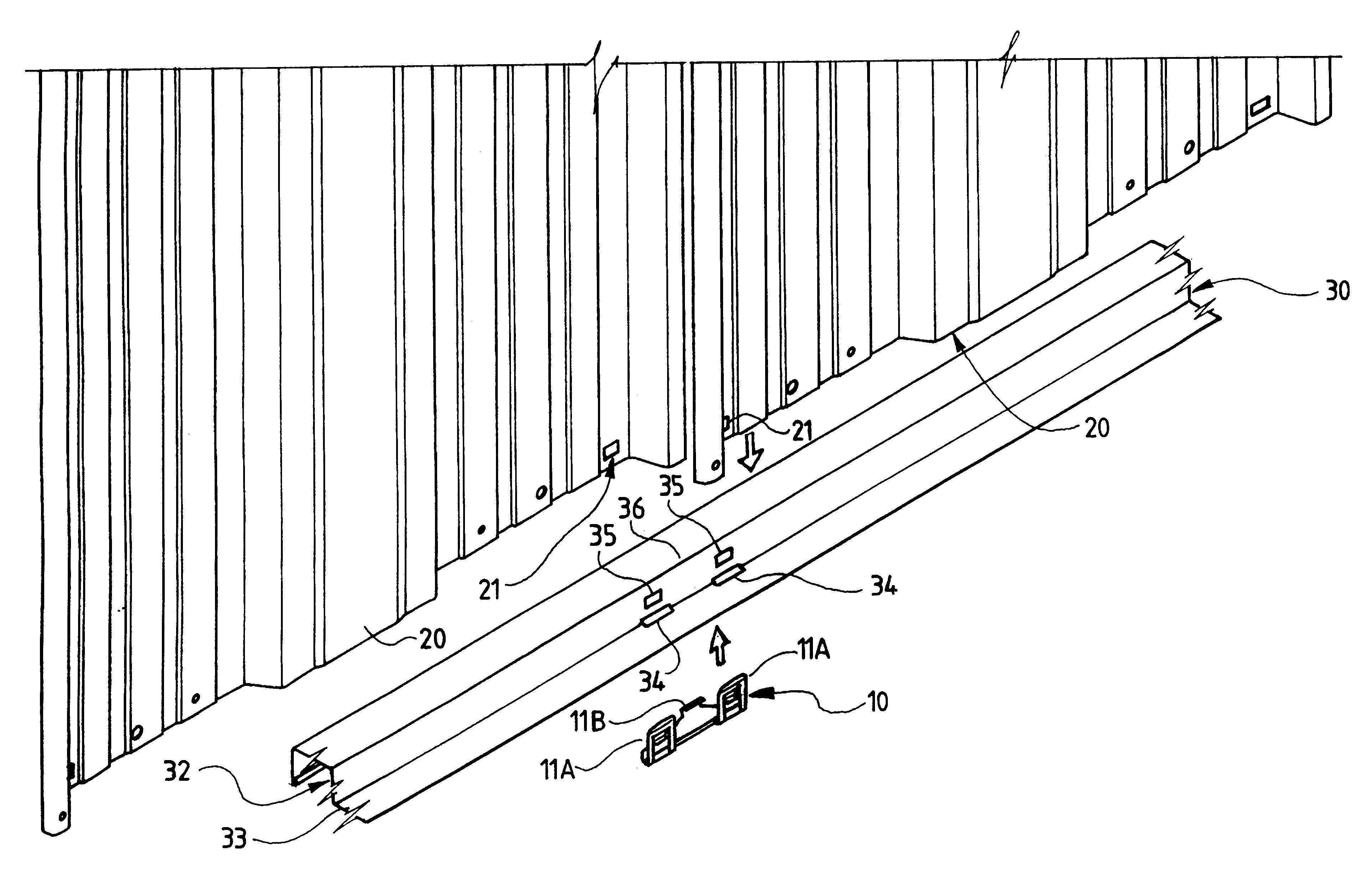
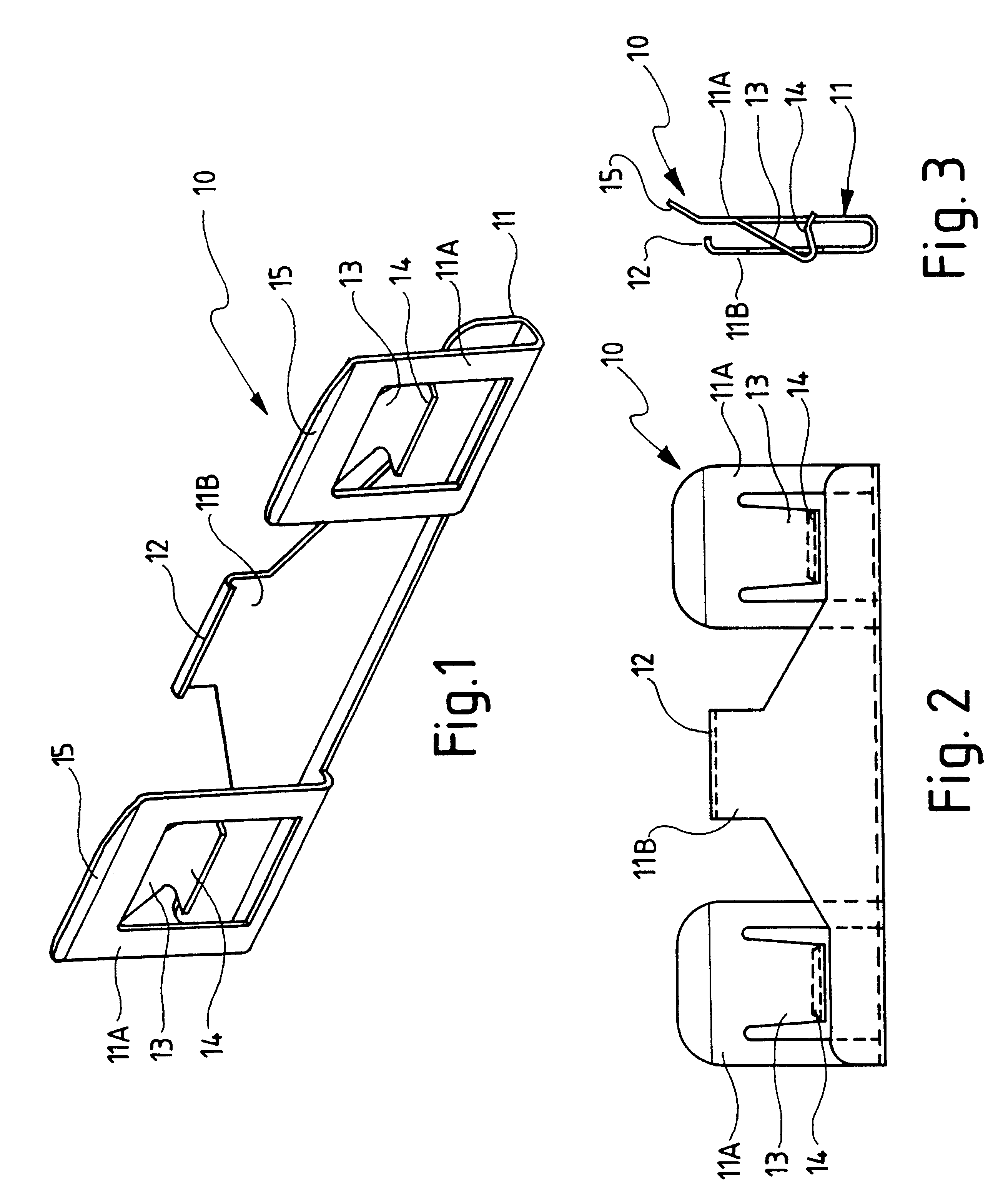
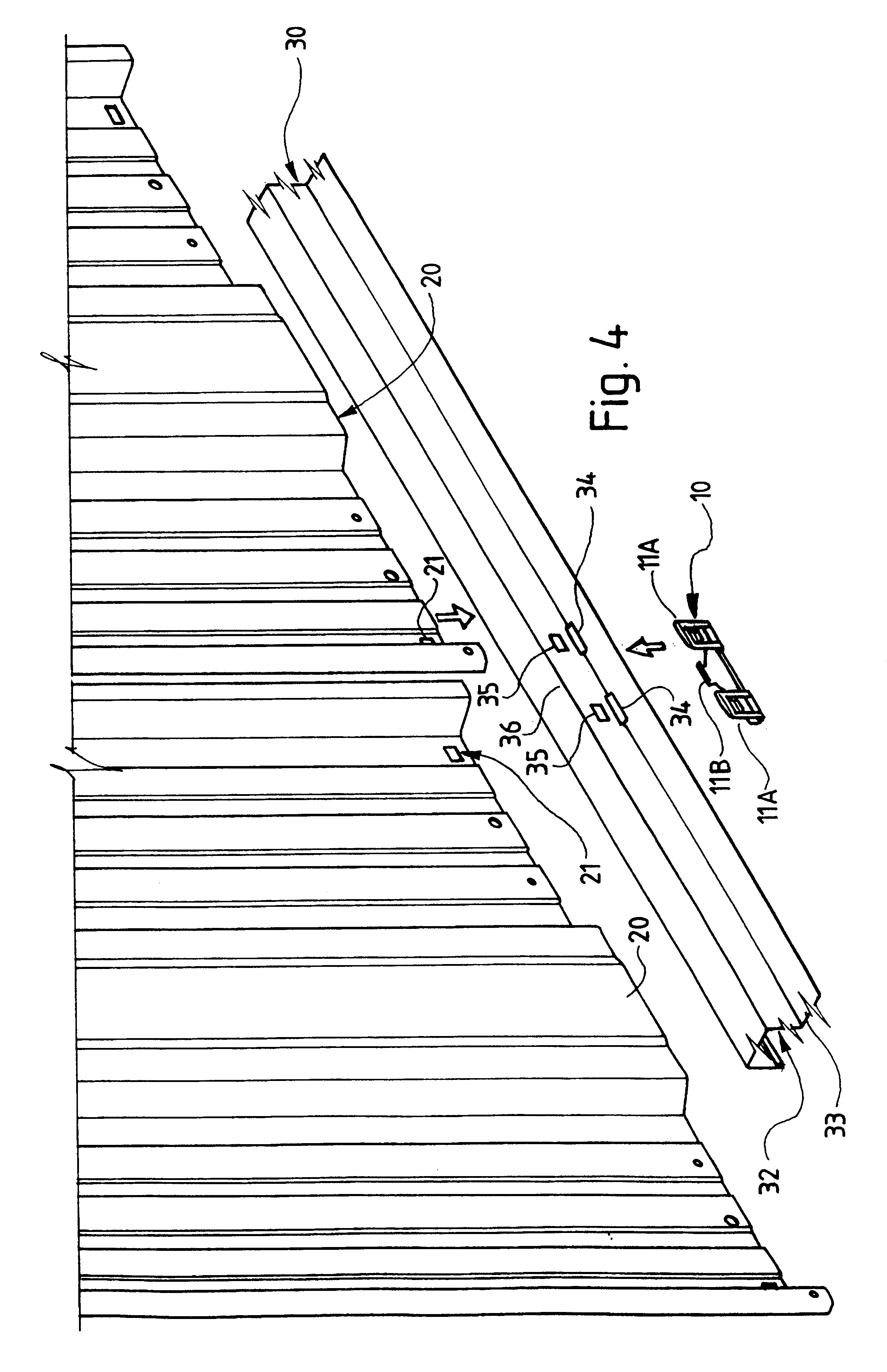
As shown in FIGS. 1-3, a fastening clip 10 is in the form of a generally U-shaped body 11. One side of the body 11 has two spaced riser portions 11A, while the other side of the body 11 has a single riser portion 11B located between the two portions 11A, as shown in FIG. 1

The upper edge of portion 11B is turned inwardly to form a lip 12 which has a hook-like function, as described below. Each portion 11A has a punched out tab 13 which is bent inwardly towards the other side of the clip, to form a pawl-like formation, as shown in FIG. 3. The tab 13 has a return portion 14 at its bottom. Each portion 11A also has an angled flange 15 at its top.

The clip 10 is typically formed from metal sheet which is generally stiff, but has a suitable degree of resilient flexibility. The clip is normally made by punching and pressing operations.

The clip 10 can be used to fasten wall panels to frame members in the erection or assembly of small metal buildings, such as garden sheds. FIGS. 4-7 illustrat...


PUM


Abstract

A clip is used to fasten a wall panel to a frame rail. The clip is fitted to the rail and has paul-like tabs which locate in apertures in a side wall of the rail. Corresponding apertures are provided on the edge of the wall. When the edge of the wall is inserted into the clip, the pawl-like tabs snap-fit through the apertures and into the apertures, thereby captively retaining the wall to the rail. Alternatively, the clip may be formed integrally with a rail by pressing out a flap from a side wall of the rail. Each flap has a pawl-like indent. Corresponding apertures are provided on the edge of a wall sheet. When the edge of the wall sheet is inserted between the flaps and the rail, the pawl-like indents locate in the apertures, thereby captively retaining the wall sheets to the rail.

Description

THIS INVENTION relates to a clip fastening system. The invention is particularly, but not solely, directed to the use of clip-like fittings to fasten metal wall sheets to top and bottom rails of a frame, to thereby facilitate the assembly and erection of prefabricated small structures or buildings such as garden sheds, garages, shadehouses, aviaries and the like.Many small structures, such as garden sheds, storage sheds, cubby houses, etc., are sold in kit form for assembly by the customer. The assembly or erection of such structures usually requires the customer to fasten wall sheets to frame components, such as top and bottom rails. Such components are normally fastened together by rivets or screws.The screwing or riveting of wall sheets is tedious and time consuming. Such methods of fastening may also require two persons, one to hold the components in place, and the other to screw or rivet them together. Furthermore, many customers do not have a rivet gun readily available. For t...

Claims


Application Information

Patent Timeline
IPC IPC(8): E04B1/343
CPCE04B1/34315
Inventor TRENOWETH, MARK GRAHAME
Owner SPANBILT AUSTRALIA
Why Eureka
Try Eureka