Feedback control for auto-ignition two-stage combustion of gasoline in engine cylinder

a two-stage combustion and feedback control technology, applied in the direction of electric control, machines/engines, mechanical equipment, etc., can solve the problems of increased labor and cost for maintenance of such hardware, and difficulty in suppressing the cost increase due to additional hardwar

Inactive Publication Date: 2003-12-09
NISSAN MOTOR CO LTD
View PDF12 Cites 63 Cited by
  • Summary
  • Abstract
  • Description
  • Claims
  • Application Information

AI Technical Summary

Problems solved by technology

The known technique is satisfactory to some extent, however, involves a potential problem that it would be difficult to suppress cost increase due to additional hardware and avoid additional labor and cost for maintenance of such hardware.

Method used


Image

  • Feedback control for auto-ignition two-stage combustion of gasoline in engine cylinder
  • Feedback control for auto-ignition two-stage combustion of gasoline in engine cylinder
  • Feedback control for auto-ignition two-stage combustion of gasoline in engine cylinder

Examples


Embodiment Construction

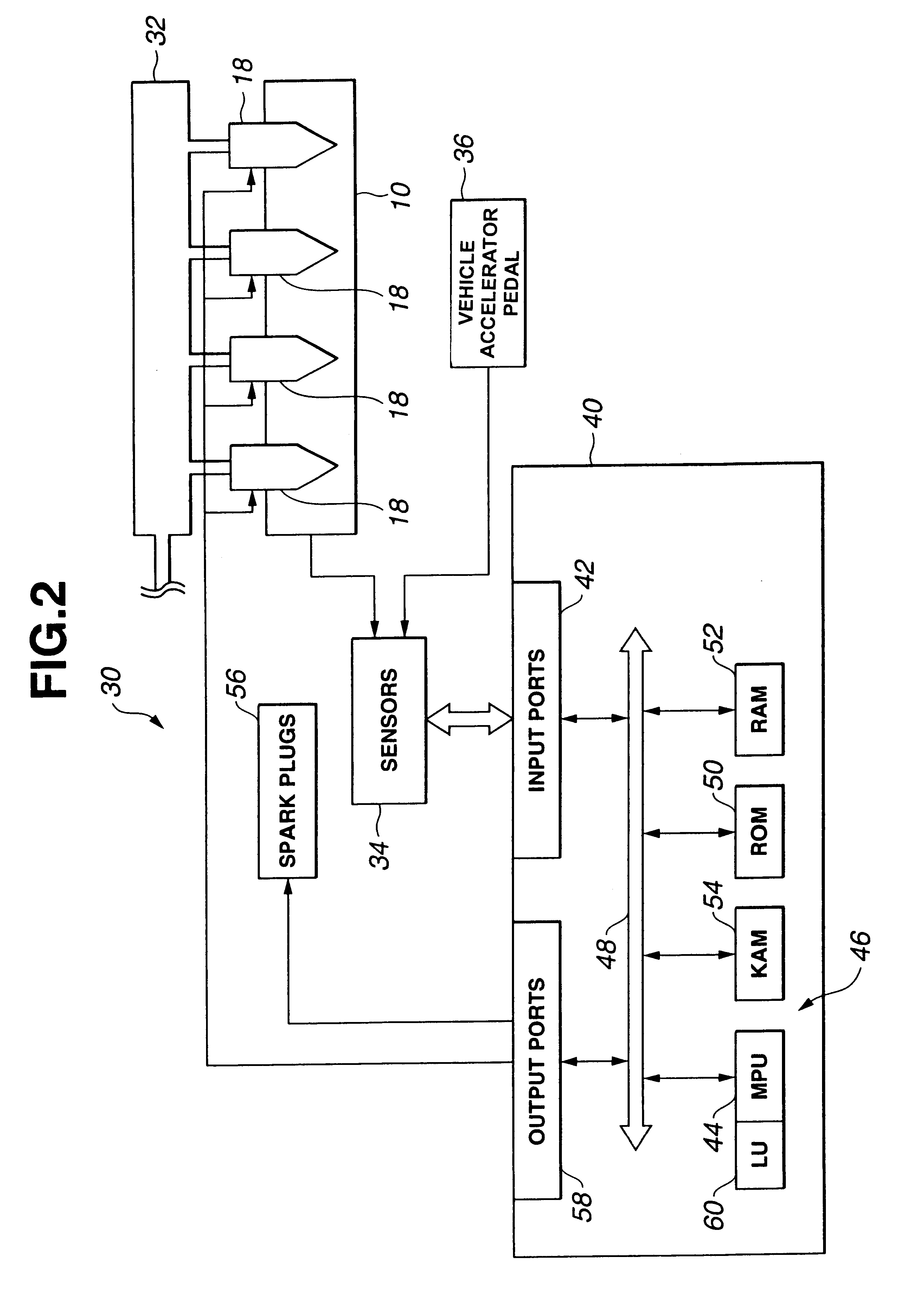
Referring now to FIG. 2, a system for controlling an auto-ignition type internal combustion engine is shown. The system, generally indicated by reference numeral 30, includes an engine 10 having a plurality of cylinders each fed by fuel injectors 18. The fuel injectors 18 are shown receiving pressurized gasoline fuel from a supply 32 which is connected to one or more high or low pressure pumps (not shown) as is well known in the art. Alternatively, embodiments of the present invention may employ a plurality of unit pumps (not shown), each pump supplying fuel to one of the injectors 18.

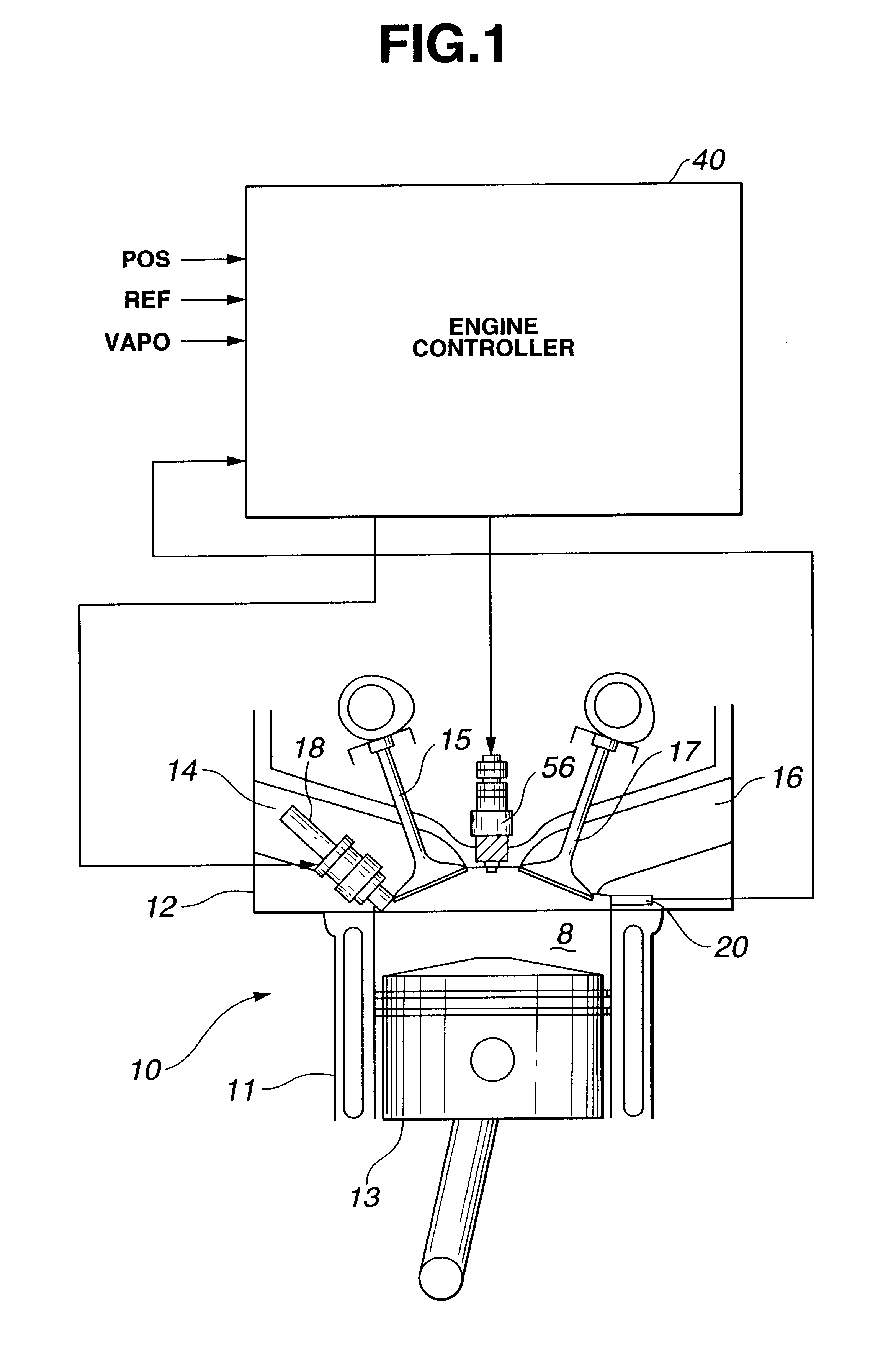
Referring also to FIG. 1, in a preferred embodiment, engine 10 is a four-stroke cycle internal combustion engine capable of running under auto-ignition combustion of gasoline fuel and under spark-ignition combustion of gasoline fuel as well. The engine 10 includes a cylinder block 11 formed with a plurality of cylinders, only one being shown. A cylinder head 12 is attached to cylinder block 11 and clos...


PUM


Abstract

A split injection of gasoline produces stratified charge in at least one cylinder. A sensor measures cylinder pressure or knock and generates a sensor signal indicative of combustion event timing of stratified charge. From the sensor signal, a controller determines an actual value of a characteristic parameter representing combustion event timing in the cylinder. The controller modifies at least one of operating variables governing a split injection for the subsequent cycle in such a direction as to decrease a deviation between the actual value of the characteristic parameter and a target value thereof toward zero.

Description

1. Field of the InventionThe present invention relates to a system and method for controlling auto-ignition combustion of gasoline in an internal combustion engine, and an auto-ignition type internal combustion engine.2. Description of Related ArtIn auto-ignition combustion of gasoline fuel, burning velocity and / or combustion initiation determine combustion event. JP-A 10-196424 discloses a technique to adjust combustion initiation time at around top dead center (TDC) of exhaust stroke of a piston.The known technique is satisfactory to some extent, however, involves a potential problem that it would be difficult to suppress cost increase due to additional hardware and avoid additional labor and cost for maintenance of such hardware.Thus, there would be a need for fine and accurate control of combustion event initiated by auto-ignition without relying on such additional hardware.An object of the present invention is to control combustion event initiated by auto-ignition without any a...

Claims


Application Information

Patent Timeline
Patent Type & Authority Patents(United States)
IPC IPC(8): F02D35/02F02D41/40F02D41/30F02B1/12F02B1/00F02B75/00F02F1/24F02B75/12F02B11/00F02D41/02F02D41/22F02D41/34F02D45/00
CPCF02B1/12F02D35/023F02D35/027F02D41/3047F02D41/401F02D35/028F02B2075/125Y02T10/123F02F2001/245Y02T10/44Y02T10/12Y02T10/40
Inventor URUSHIHARA, TOMONORIYOSHIZAWA, KOUDAIHIRAYA, KOJI
Owner NISSAN MOTOR CO LTD
Why Eureka
Try Eureka