
Vehicle motion control device and method

a technology of motion control device and vehicle, which is applied in the direction of process and machine control, instruments, tractors, etc., can solve the problems of behavior instability, late or insufficient suppression effect, and inability to detect abnormal running behavior, so as to avoid wheel spin and wheel lock phenomena, efficiently and surely stabilize the vehicle running, and efficiently detect abnormal running behavior

Inactive Publication Date: 2003-12-09
TOYOTA JIDOSHA KK
View PDF16 Cites 80 Cited by
  • Summary
  • Abstract
  • Description
  • Claims
  • Application Information

AI Technical Summary

Benefits of technology

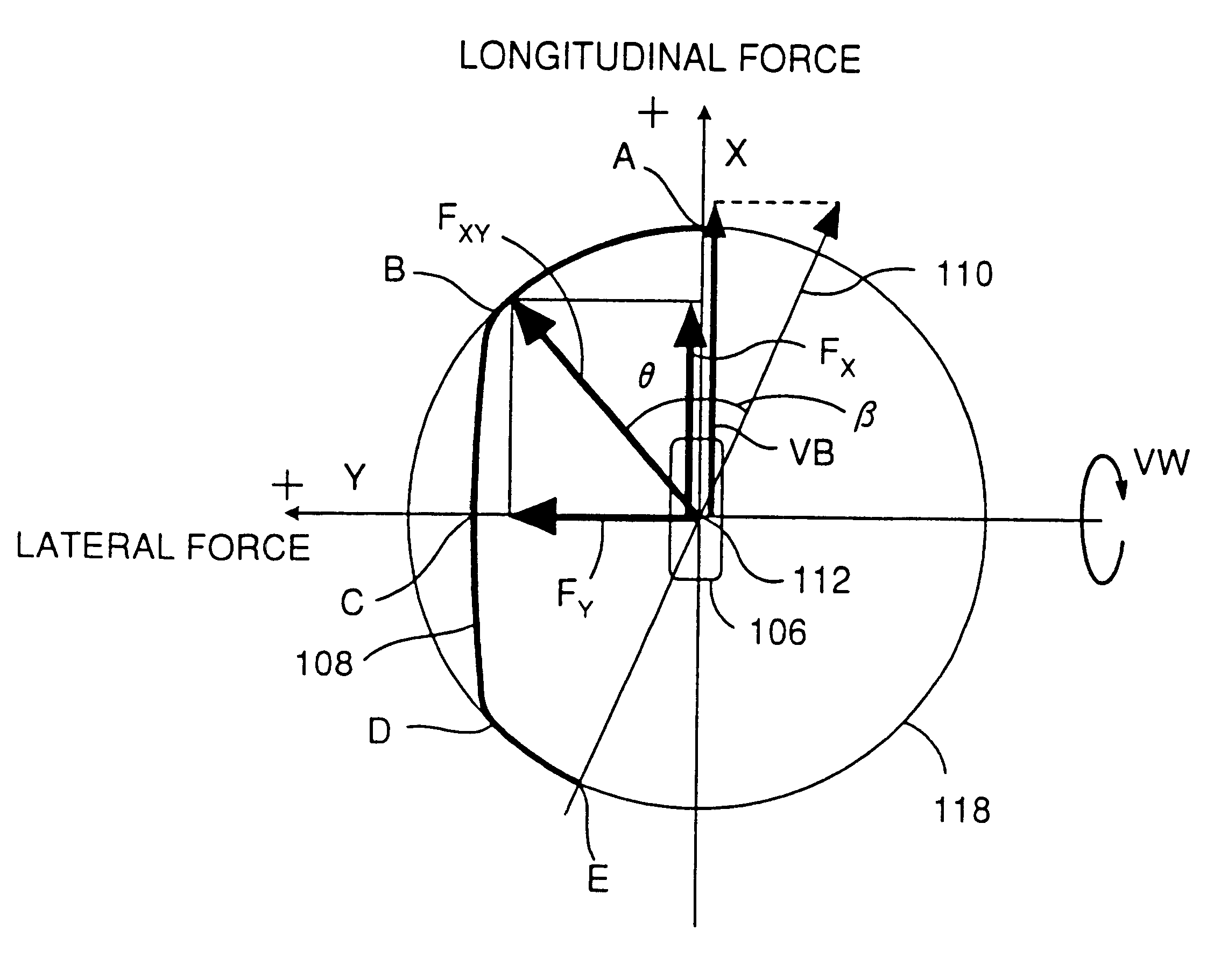
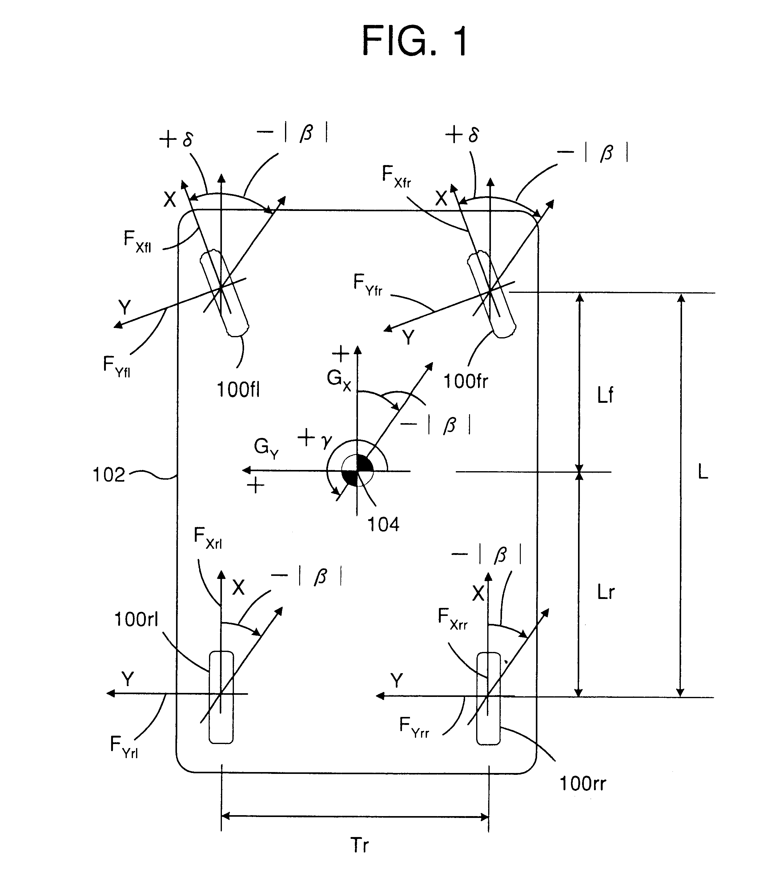
According to the present invention, a device for controlling a running behavior of a vehicle comprises means for estimating a road reaction force generated on each of the wheels, means for calculating a yaw moment around a centroid of the vehicle body generated by the road reaction force on each of the wheels, and means for controlling driving and braking forces on each of the wheel based upon the yaw moments so as to stabilize the running of the vehicle. In this device, the running of the vehicle is efficiently and surely stabilized based upon a yaw moment actually generated by a road reaction force on each wheel by monitoring the road reaction forces on each of the wheels, instead of depending upon an index value based upon only a total vehicle running condition as in a conventional motion controlling device.
It is another object of the present invention to provide such devices and methods wherein a yaw moment required for stabilizing the vehicle running is calculated from presently generated yaw moments and critical yaw moments, thereby allowing for the critical limits of the road reaction force on each of the wheels in the calculation of the required yaw moment.

Problems solved by technology

Thus, the suppression effect could be late or insufficient for an extensive deterioration.
Such deteriorated conditions at any of wheels would easily lead to the behavior instability.

Method used


Image

  • Vehicle motion control device and method
  • Vehicle motion control device and method
  • Vehicle motion control device and method

Examples


first embodiment

II-1. First Embodiment

(A Four Wheel Drive Vehicle with an Engine Control)

FIG. 23 diagrammatically shows a four-wheel drive vehicle incorporating a vehicle motion control device according to the present invention. The vehicle includes a vehicle body 12, front right wheel 24FR, front left wheel 24FL, rear right wheel 24RR and rear left wheel 24RL supporting the vehicle body 12 via the respective suspension means (not shown in the figure), an engine 10 adapted to output a driving torque according to a throttle valve opening in response to the depression of an acceleration pedal 51 by the driver, and a transmission 16 providing a driving force to the wheels through a differential gear system 62-70 and front and rear wheel shafts 22R, L and 56R, L. The differential gear system includes a center differential gear device 62 adapted to distribute a driving torque received through an output shaft 60 of the transmission 16 to front and rear propeller shafts 64, 66, respectively, and front and...

second embodiment

The second embodiment is identical to the first embodiment except that no modulation of engine output of the sub-routine as shown in FIG. 28 is done. Thus, step 220 is bypassed. In step 240, a driving force D obtained from expression (3, 4) is substituted in expression (5.99).

third embodiment

II-3 Third Embodiment

(A Rear Wheel Drive Vehicle With an Engine Control)

The vehicle motion control device according to the present invention may be incorporated in a rear wheel drive vehicle. Referring again to FIG. 23, in a rear wheel drive vehicle, as well-known in the art, the front wheels are free of a driving force, and thus, there is no system transmitting the engine torque to the front wheels, corresponding to wheel shafts 56R and L, center differential gear device 62, front propeller shaft 64, front differential gear device 68. The front wheels may rotate independently of each other. The other structures in the rear wheel drive vehicle are substantially identical to those diagrammatically shown in FIG. 23.

The protocols of the vehicle motion control for the rear wheel drive vehicle according to the present invention are substantially similar to those for the four wheel drive vehicle as described above. In the followings, the differences in the protocols from those for the fou...


PUM


Abstract

Vehicle motion control devices and methods systematically treat a conditions of each wheel to acquire and maintain the vehicle behavior stability together with anti wheel lock and wheel spin processing, braking forces distribution. Device for controlling a running behavior of a vehicle estimates a road reaction force on each wheel, calculates a yaw moment around a centroid of the vehicle body generated by the road reaction force on each wheel, and controls driving and braking forces on each wheel based upon the yaw moments so as to stabilize a running of the vehicle. Spin and Drift conditions are detected through presently generated yaw moments and critical yaw moments which can be generated by a road reaction force assumed to be maximized. Physical parameters of each wheels, required for detecting and controlling the behavior of the vehicle are estimated with a theoretical tire model.

Description

1. Field of the InventionThe present invention relates to a device and a method for controlling a motion of a vehicle such as an automobile, and more specifically, to such a device that controls driving and braking forces applied to wheels of a vehicle to stabilize the behavior of the vehicle during turn driving.2. Description of Prior ArtIn a modern automobile, a motion of a vehicle, such as a turning behavior of the vehicle body, is stabilized by an electronic controlling system monitoring vehicle running conditions such as a vehicle velocity, longitudinal and lateral accelerations, a yaw rate and a steering angle. When an undesirable condition such as a spin and a drift-out occurs, the controlling system cooperates with driving and braking systems to generate an appropriate driving or braking force on a particular wheel, which induces a yaw moment on the vehicle body (around its centroid) against the spin or drift-out condition, thereby maintaining an appropriate yaw rate of the ...

Claims


Application Information

Patent Timeline
Patent Type & Authority Patents(United States)
IPC IPC(8): B60T8/17B60T8/1755B60T8/172B60T8/58B60W10/04B60W10/06B60W10/12B60W10/18B60W10/188B60W50/00F02D29/02
CPCB60T8/17552B60T8/1769B60W10/184B60W40/11B60W40/112B60W40/114B60T2201/14B60T2230/02B60W2050/0028B60T2270/86B60T8/58
Inventor NAKAMURA, AKIRA
Owner TOYOTA JIDOSHA KK
Learn More