Image processing method, image processing system, and modifying-data producing method

a processing method and image technology, applied in the field of processing image data, can solve the problems of reducing the resolution of the taken image, difficult to recognize accurately one or more fine parts of the ec, and the cost of the line-sensor camera itself, so as to achieve the effect of reducing the total amount of modifying data

Inactive Publication Date: 2003-12-09
FUJI MASCH MFG CO LTD
View PDF14 Cites 67 Cited by
  • Summary
  • Abstract
  • Description
  • Claims
  • Application Information

AI Technical Summary

Benefits of technology

In the case where the single image-taking device takes the substrate-part images from the parts of the standard substrate, the errors caused by the distortion of one or more components of the image-taking device (e.g., a lens or a matrix of CCDs), and the modifying amounts to modify or correct the errors, can be considered as being common to all of the physical screens. Hence, the present modifying-data producing method produces the modifying data including the image-distortion data which can be used commonly to all the physical screens, and the positional-error data representing the positional error of each of the physical screens. Thus, the total amount of the modifying data can be reduced as compared with the case where the modifying tables corresponding to the physical screens include respective batches of image-distortion data.

Problems solved by technology

However, when a commonly or widely used CCD camera including a limited number of CCDs or having a limited number of pixels takes, at once, a whole image of a large-size EC having a complex shape, each of the CCDs must take a pixel image of an excessively large portion of the EC, which leads to lowering the degree of resolution of the taken image.
Thus, it is difficult to recognize accurately one or more fine portions of the EC, such as its lead wires.
However, the line-sensor camera itself is expensive, and additionally needs a special high-performance light source, which leads to increasing the overall cost of the EC mounting apparatus which employs the line-sensor camera.
Moreover, the line-sensor camera needs a longer time to take the whole image of the EC.
However, in the above method in which the plurality of batches of part-image data are obtained by one or more CCD cameras, a whole or complete image of the large-size EC 200 is not taken.
Therefore, the prior method cannot inspect the EC 200 as a whole.
In fact, however, an image-taking device (e.g., a CCD camera) has a distortion of a lens (e.g., a distortion of a matrix of CCDs) and accordingly an image taken by the image-taking device may have distortions in its peripheral portions, in particular.
In addition, physical relative positions of the image-taking device or devices relative to the EC 200 may contain some positional errors from reference or prescribed relative positions.
If the part images taken from the EC 200 are connected to each other without taking into account the lens distortion or the positional errors, then it would be difficult to reproduce an accurate, whole image of the EC 200 because of the distortion and the errors.
Though the above discussion relates to the art of taking and processing images of ECs, the above problems may occur to not only the ECs but also other sorts of objects (e.g., connectors).

Method used


Image

  • Image processing method, image processing system, and modifying-data producing method
  • Image processing method, image processing system, and modifying-data producing method
  • Image processing method, image processing system, and modifying-data producing method

Examples


Embodiment Construction

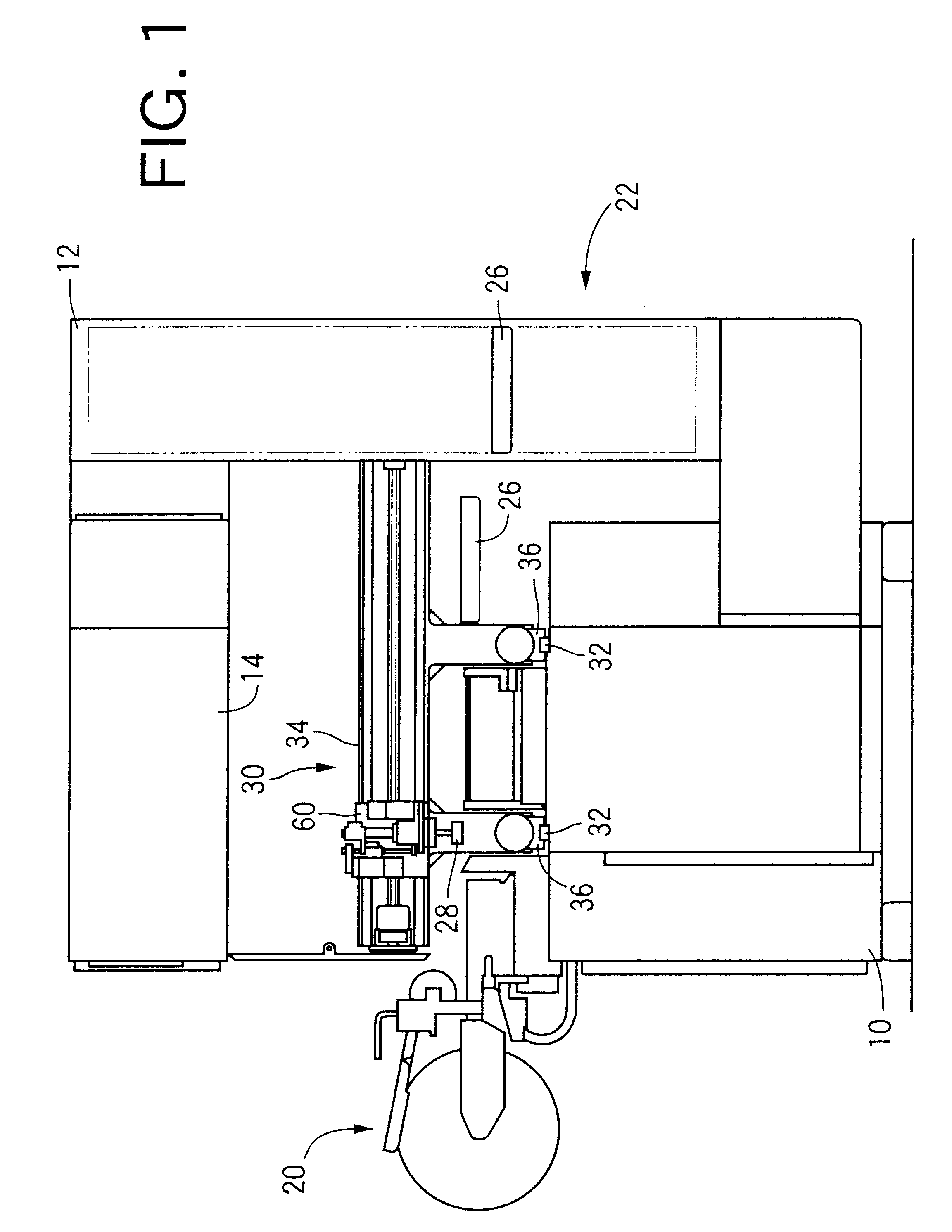
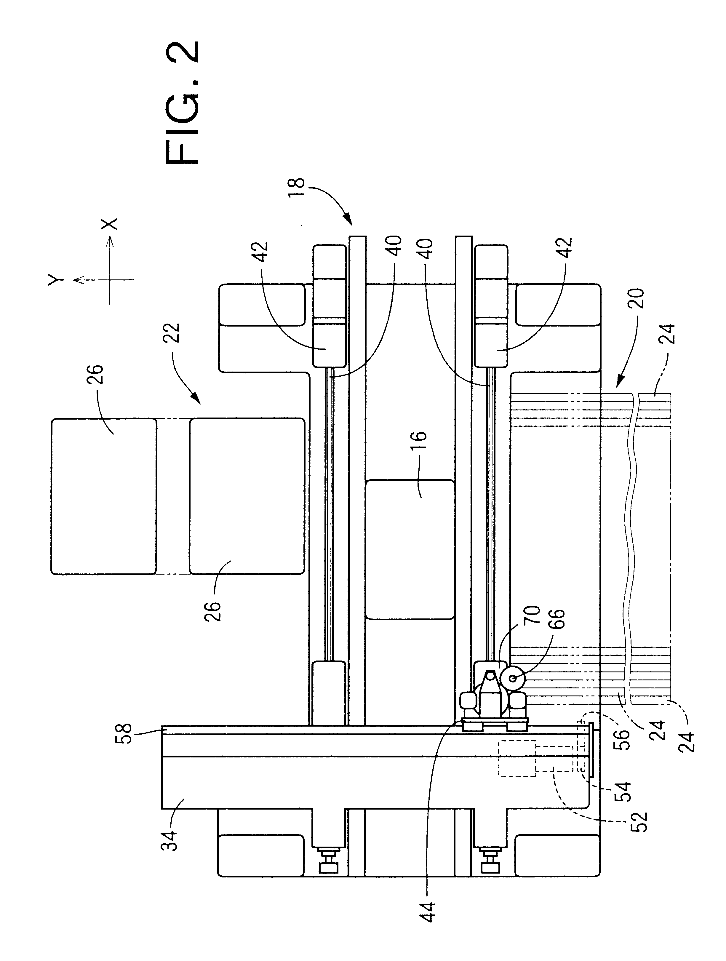
An electric-component (EC) mounting system to which the present invention is applied is shown in FIGS. 1 and 2. The present EC mounting system has the same basic construction as that of the system disclosed in Japanese Patent No. 2,824,378. First, a general construction of the EC mounting system is briefly described and then, only relevant portions of the same are described in detail.

In FIG. 1, reference numeral 10 designates a base, on which a plurality of columns 12 stand. A stationary frame 14 is fixed to the columns 12, and supports an operation panel, etc. As shown in FIG. 2, on the bed 10, there is also provided a board conveyor 18 which conveys a printed board 16 as a circuit substrate in an X-axis direction as shown in FIG. 2. The term "printed board" is used to refer both a printed "wiring" board on which no ECs have been mounted, and a printed "circuit" board on which ECs have been mounted. The printed board 16 which is conveyed by the board conveyor 18 is positioned and s...


PUM


Abstract

A method of processing batches of object-part-image data representing object-part images which are taken by one or more image-taking devices from parts of an object, respectively, and thereby obtaining one or more optical characteristic values of the object, the object-part images imaging the parts of the object such that a first object-part image images a first part and a second object-part image images a second part adjacent to the first part in the object and includes an overlapping portion imaging a portion of the first part, each of the batches of object-part-image data including optical characteristic values respectively associated with physical positions, and thereby defining a corresponding one of physical screens, the method including the steps of designating at least one virtual position on a virtual screen corresponding to the parts of the object, modifying, based on predetermined modifying data, the at least one virtual position on the virtual screen, and thereby determining at least one physical position corresponding to the at least one virtual position, on one of the physical screens, and obtaining at least one optical characteristic value associated with the at least one physical position on the one physical screen, as at least one optical characteristic value associated with the at least one virtual position on the virtual screen and as the at least one optical characteristic value of the object.

Description

BACKGROUND OF THE INVENTION1. Field of the InventionThe present invention relates to the art of processing image data representing an image taken by an image-taking device, and particularly to the art of processing a plurality of batches of image data respectively representing a plurality of images which are taken by one or plural image-taking devices from an object a whole image of which cannot be taken at once by the one image-taking device or each of the plural image-taking devices.2. Discussion of Related ArtThere is known an electric-component (EC) mounting apparatus which includes a suction nozzle for holding an EC, and an image-taking device for taking an image of the EC held by the nozzle and thereby inspecting a condition of the EC. The image-taking device may be a CCD (charge-coupled-device) camera including a matrix of CCDs for taking a whole image of the EC. Necessary information can be obtained from the taken image of the EC.However, when a commonly or widely used CCD c...

Claims


Application Information

Patent Timeline
Patent Type & Authority Patents(United States)
IPC IPC(8): G06T15/10G01B11/00G01B11/24G06T1/00G06T3/00H05K13/04
CPCG06T7/0028G06T7/0042G06T2207/30141G06T7/33G06T7/73
Inventor KAWADA, TOSUKE
Owner FUJI MASCH MFG CO LTD
Why Eureka
Try Eureka