Variable temperature vaporizer

a variable temperature, vaporizer technology, applied in the direction of manufacturing tools, lighting and heating apparatus, heating types, etc., can solve the problems of affecting the assembly process, the need for a polarized plug also tends to complicate the assembly process, and the mechanical control device is generally found to be somewhat ineffective in controlling the rate of liquid evaporation

a variable temperature, vaporizer technology, applied in the direction of manufacturing tools, lighting and heating apparatus, heating types, etc., can solve the problems of affecting the assembly process, the need for a polarized plug also tends to complicate the assembly process, and the mechanical control device is generally found to be somewhat ineffective in controlling the rate of liquid evaporation

US6661967B2Inactive Publication Date: 2003-12-09HENKEL IP & HOLDING GMBH

Image

  • Variable temperature vaporizer
  • Variable temperature vaporizer
  • Variable temperature vaporizer

Examples


Embodiment Construction

The following descriptions are of exemplary embodiments of the invention only, and are not intended to limit the scope, applicability, or configuration of the invention in any way. Rather, the following description is intended to provide convenient illustrations for implementing different embodiments of the invention. As will become apparent, various changes may be made in the function and arrangement of the elements described in these embodiments without departing from the spirit and scope of the invention. For example, various changes may be made in the design and arrangement of the elements described in the preferred embodiments without departing from the scope of the invention as set forth in the appended claims.

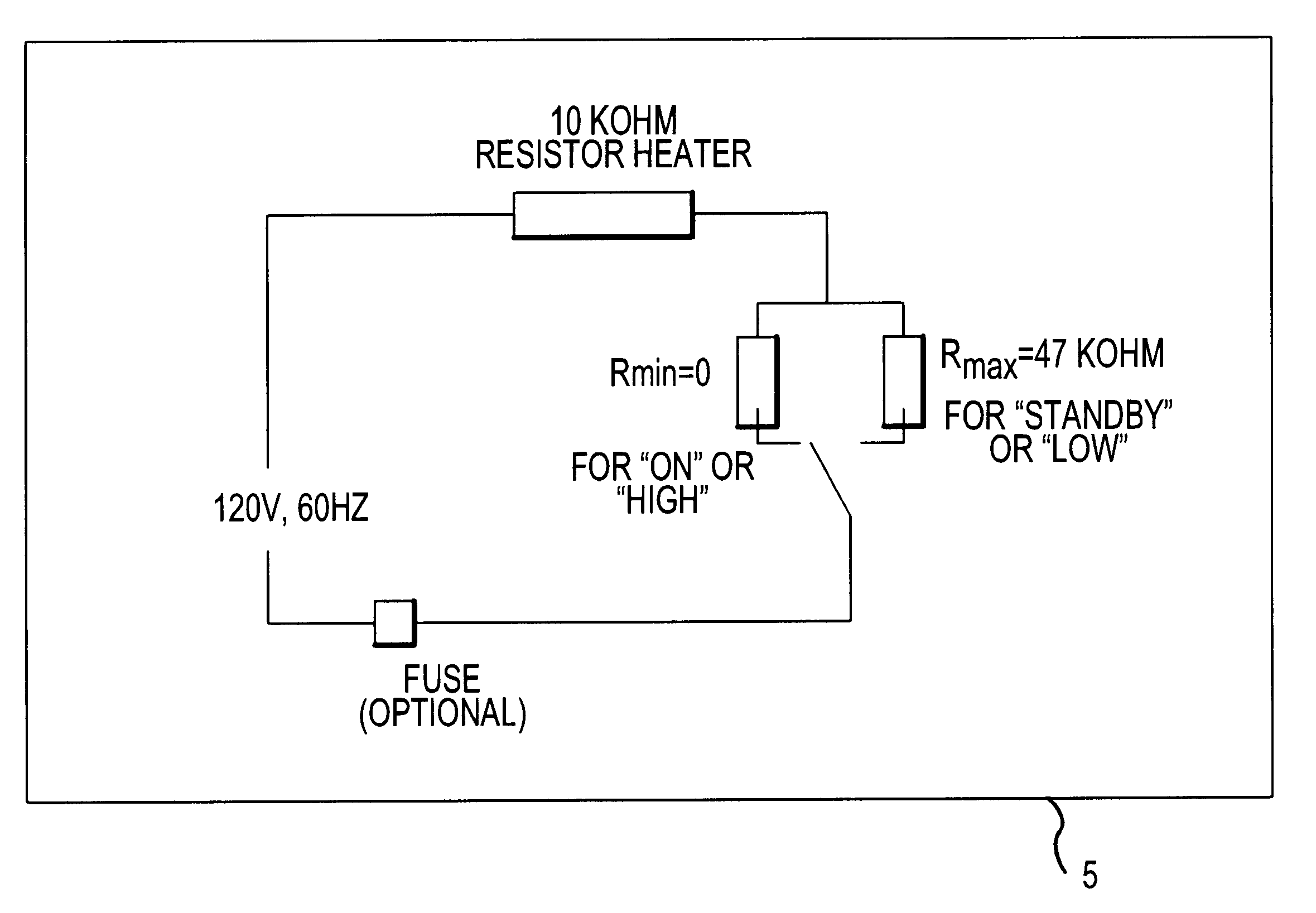
In general, the present invention provides a method for controlling the temperature and / or the rate of evaporation of a volatile liquid in a vaporizer device. For example, as described further herein and in accordance with various exemplary embodiments of the present inv...


PUM

PropertyMeasurementUnit
temperatureaaaaaaaaaa

Abstract

The present invention suitably provides a method and apparatus for controlling the temperature of a liquid vaporizer heating element, and thereby the rate of evaporation and level of fragrance delivery from the same. In accordance with one exemplary embodiment of the present invention, the device may include a switch that suitably allows the temperature of various types of heating elements to be controlled for different levels of fragrance output. For example, an exemplary embodiment may include a two-pronged plug adaptable to typical outlets that might be found in residential homes or businesses. In accordance with another exemplary embodiment of the present invention, the electrical switch generally provides varying resistance values to the electric circuitry of the vaporizer such that, by changing the switch setting, the operating temperature of the wick is controlled and thus the rate of fragrance evaporation from the vaporizer.

Description

1. Field of the InventionThe present invention relates generally to liquid vaporizers for dispensing volatile liquid materials such as fragrance oils and solutions, deodorants, insecticides and the like, and, more particularly, the present invention relates to a method and apparatus for controlling the rate of liquid evaporation.2. Background of the InventionElectrical liquid vaporizers (often referred to as "liquid electrics") are generally well known in the prior art. Typically, such electric liquid vaporizers comprise a housing unit configured to receive a bottle or liquid container portion. The bottle portion contains a wick or wicking system through which the volatile liquids can be migrated to a portion of the wick that is exposed to the air. The exposed portion of the wick is generally heated by a heating element disposed within the housing unit and proximate to the wick in order to suitably facilitate the vaporization of the volatile liquid to be dispensed therefrom.Various ...

Claims


Application Information

Patent Timeline
09 Dec 2003
Publication
US6661967B2
IPC
A61L9/02; A61L9/015; A61L9/03; F24F6/10; F24F6/02; H05B1/02; A01M1/20
CPC
A01M1/2077; A61L9/02; A61L9/037; F24F6/10; H05B1/0244; H05B1/0252; H05B2203/022; H05B2203/021
Inventors
LEVINE, LAWRENCE T.; STATHAKIS, KRISTOPHER J.