Rotary pump

a rotary pump and rotor technology, applied in the direction of rotary piston engines, rotary or oscillating piston engines, liquid fuel engines, etc., can solve the problems of loss of efficiency, rotors being difficult to turn and wear of contact surfaces, and high friction between these surfaces

Inactive Publication Date: 2003-12-23
IC INNOVATIONS
View PDF18 Cites 44 Cited by
  • Summary
  • Abstract
  • Description
  • Claims
  • Application Information

AI Technical Summary

Problems solved by technology

This means that the contact between the stator inner liner and rotor vanes must be good and therefore friction between these surfaces tends to be high.
A high friction contact between the surfaces results in the rotor being difficult to turn and to wear of the contact surfaces.
A disadvantage of this approach is that the oil mixes with the fluid as it is compressed by the pump, with several undesirable consequences.
The fluid and oil mixture must be separated downstream of the rotary pump, which is an expensive process,

Method used


Image

  • Rotary pump
  • Rotary pump
  • Rotary pump

Examples


Embodiment Construction

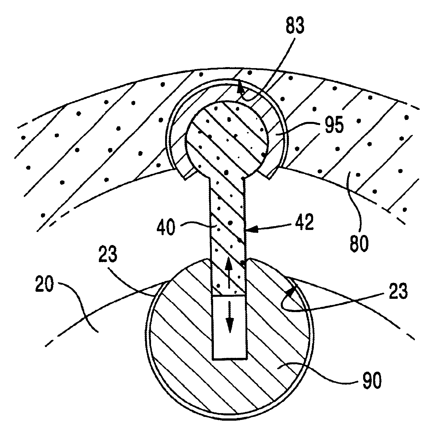
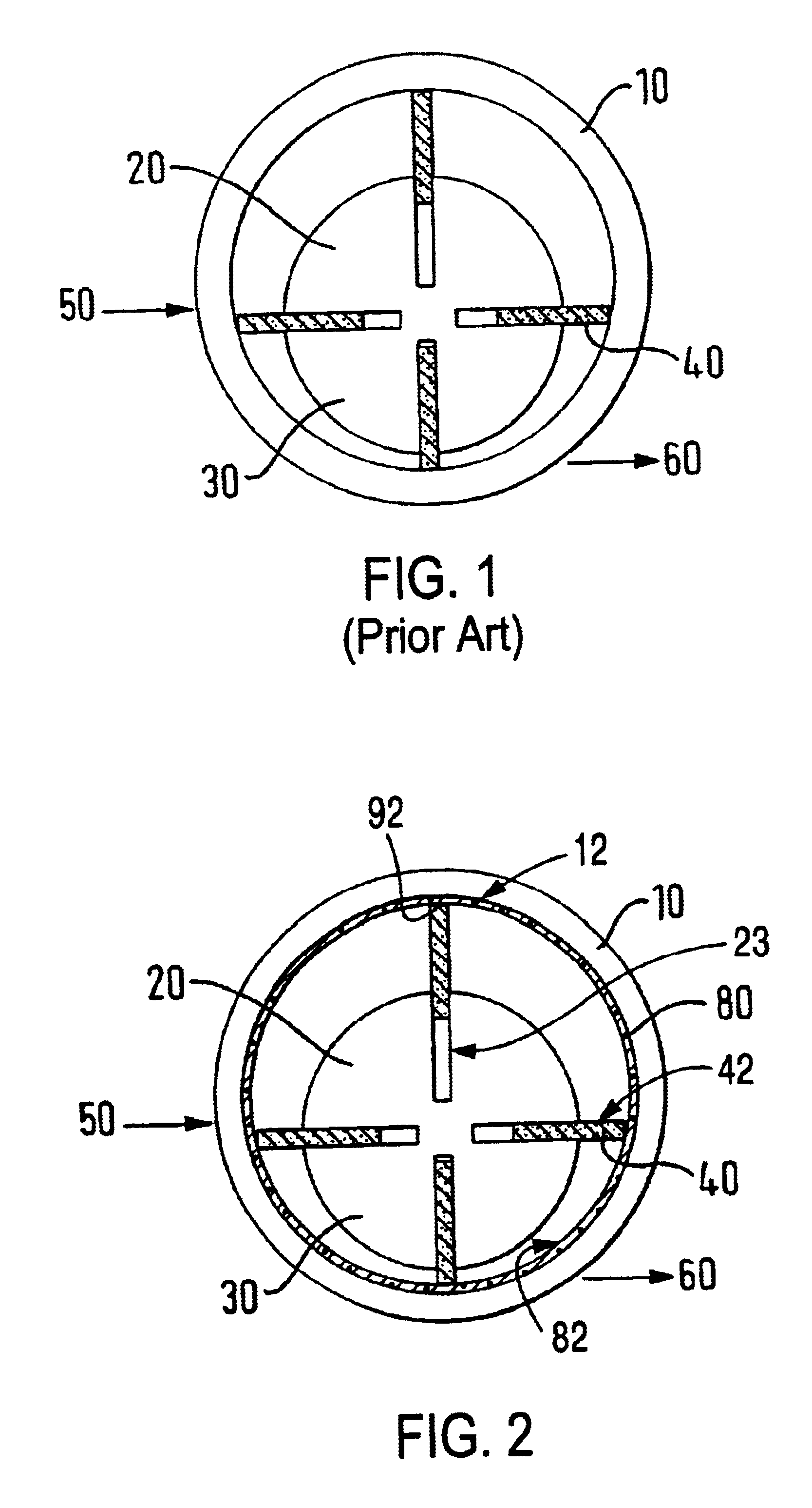
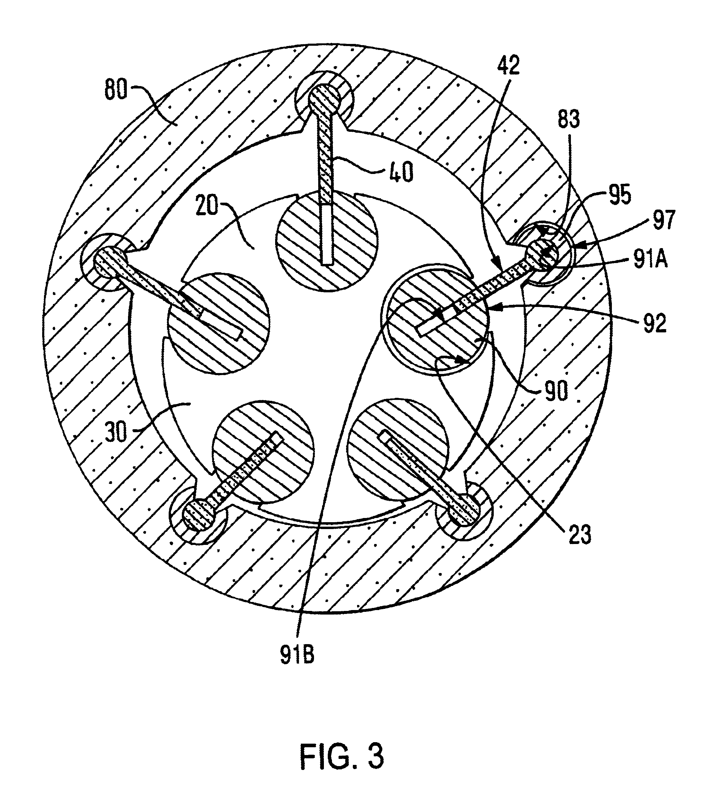
With reference to FIG. 2, a rotary pump illustrates the principle or the rotating stator inner liner is illustrated. This pump comprises a stator 10, a rotor 20 with rotor main body 30 and vanes 40, a fluid inlet 50 and outlet 60 and a stator inner liner 80 is shown. The pump differs from the pump shown in FIG. 1 in that it additionally comprises a stator inner liner 80. The stator inner liner 80 is mounted within the main stator body 10 and is free to rotate. The vanes 40 of the rotor 20 contact the stator inner liner 80 rather than the stator main body 10.

As the rotor turns the vanes 40 sweep along the surface of the stator inner liner 80. The vanes 40 exert a rotational torque on the stator inner liner 80, which is mounted such that it is free to rotate, and this causes it to rotate. The dimensions of the stator inner liner 80 are such that there is a gap between the stator main body 10 and the stator inner liner 80. A bearing can be provided between the stator main body 10 and t...


PUM

PropertyMeasurementUnit
Angleaaaaaaaaaa
Radiusaaaaaaaaaa
Velocityaaaaaaaaaa

Abstract

A rotary pump for pumping compressible fluid comprising an eccentrically mounted rotor 20 and a stator 10. The stator 10 comprises a stator inner liner 80 that is free to rotate, driven directly or in response to rotation of the rotor 20 such that the relative velocity between the outer surface of the rotor 20 and the inner surface of the stator 10 is reduced. The vanes 40 are held at each end by sockets 90, 95 in the rotor 20 and stator 10. The vane 40 and socket 90, 95 coupling provides fluid sealing without liquid lubricant. Opposing solid lubricant and hard surfaces are used on contact surfaces between the elements.

Description

This application is the U.S. national phase of international application PCT / GB00 / 02150 filed Jun. 2, 2000, which designated the U.S.1. Field of the InventionThis invention relates to rotary pumps.2. Discussion of Prior ArtRotary pumps are known devices that are used in a wide range of applications to pump fluids from one place to another and to compress them. A known rot is shown in FIG. 1 of the accompanying drawings. This pump comprises a stator 10 and a rotor 20, the rotor being eccentrically mounted within the stator. The rotor comprises a main body 30 with vanes 40 extending from the main body. The vanes are slideably mounted on the rotor main body such that they can be pushed back into the main body against an outward bias. When the rotor is eccentrically mounted within the stator as shown in FIG. 1, the vanes extend out from the rotor and contact the inner surface of the stator. Due to the eccentric mounting of the rotor the radial extension of each vane varies with angular ...

Claims


Application Information

Patent Timeline
IPC IPC(8): F01C21/10F01C21/00F01C21/08F04C18/30F04C18/336
CPCF01C21/0809F04C18/336F01C21/104F05C2225/04
Inventor OLVER, ANDREW VERNONCONTALDI, GIULIO FRANCESCO
Owner IC INNOVATIONS
Why Eureka
Try Eureka