
Device for hydraulically adjusting the angle of rotation of a shaft relative to a driving wheel

a technology of hydraulic adjustment and crankshaft, which is applied in the direction of mechanical equipment, machines/engines, couplings, etc., can solve the problems of high cost, high cost, complex and therefore cost-intensive finishing, and achieve the effect of simple and more economical manner

Inactive Publication Date: 2003-12-30
SCHAEFFLER TECH AG & CO KG
View PDF12 Cites 21 Cited by
  • Summary
  • Abstract
  • Description
  • Claims
  • Application Information

AI Technical Summary

Benefits of technology

It is an object of the invention to provide a device for hydraulic angular adjustment, particularly of a camshaft relative to a crankshaft, which can be manufactured in a simpler and more economic manner than conventional devices.

Problems solved by technology

A drawback of this device is that it is relatively expensive due to the need of vane rotors.
If these vane rotors that have a relatively complex shape are made, for example by sintering, precisely defined fabrication methods must be used, and a further drawback is that a very complex and therefore cost-intensive finishing is required.
Consequently, this solution is also relatively complex and expensive.

Method used


Image

  • Device for hydraulically adjusting the angle of rotation of a shaft relative to a driving wheel
  • Device for hydraulically adjusting the angle of rotation of a shaft relative to a driving wheel
  • Device for hydraulically adjusting the angle of rotation of a shaft relative to a driving wheel

Examples


Embodiment Construction

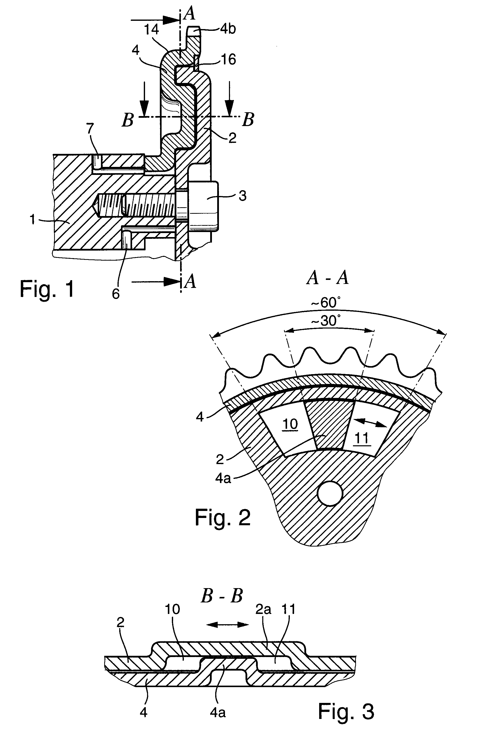
In a first preferred embodiment of the device of the invention, the shaped section in the plate that is connected rotationally fast to the camshaft is configured as a pocket or cavity, and the dividing means that cooperates with the shaped section for forming the two separate chambers is configured on the drive pinion as a ring-segment shaped projection that engages the pocket, the angular extent of the projection being smaller than the angular extent of the ring-segment shaped section of the first plate. In this embodiment, both the plate that is connected rotationally fast to the camshaft as well as the drive pinion can be manufactured by very simple fabrication methods. In a simple manner, shaping techniques can be used in the case of metallic materials and injection molding methods in the case of plastics. By making the angular extent of the projection smaller than the angular extent of the shaped section, a range of adjustment within which an angular adjustment is to be effecte...


PUM


Abstract

The invention concerns a device for the hydraulic adjustment of the angular position of a shaft (1) relative to a drive pinion (14), said device comprising a plate (2) fixed to the shaft to cooperate with the drive pinion (14) or with a component fixed to the drive pinion. The device comprises at least one ring-segment shaped section (2a) in the plate (2) and a means (4a) arranged on the drive pinion (14) or on said component to cooperate with the shaped section (2a) so as to divide the shaped section into two separate chambers (10, 11). The device further comprises a means for a selective hydraulic pressurization of the chambers (10, 11) for adjusting the relative angular position of the drive pinion (14) and the shaft (1).

Description

The invention concerns a device for a hydraulic adjustment of the angular position of a shaft relative to a drive pinion, said device comprising a plate fixed to the shaft to cooperate with the drive pinion for adjusting the angular position.A device of the pre-cited type is known, for example, from U.S. Pat. No. 3,109,417. In this and other known devices, vanes of a vane rotor divide each cell of a cell rotor into two chambers sealed relative to each other, at least one of which chambers can be pressurized. When the engine is turned off, the pressure medium flows out of the chambers through supply or discharge ducts and leak gaps.Another device for hydraulically adjusting the angular position of a shaft, particularly a camshaft of an internal combustion engine, relative to a drive pinion is known from DE 39 37 644 A1. This device comprises a vane rotor that is fixed to the shaft and comprises radial vanes, and a cell rotor arranged on the drive to receive the vanes in circumferenti...

Claims


Application Information

Patent Timeline
IPC IPC(8): F01L1/344
CPCF01L1/3442Y10T74/2102F01L2101/00F01L2001/34479F01L2301/00
Inventor SCHEIDT, MARTINSCHAFER, JENSNELLER, DIETER
Owner SCHAEFFLER TECH AG & CO KG
Learn More