Cable network repair control system

a network repair and control system technology, applied in transmission, telephonic communication, non-redundant fault processing, etc., can solve the problems of system passive operation, little integration with the network itself and with resources,

Inactive Publication Date: 2003-12-30
LAKEFIELD ETECH GROUP
View PDF18 Cites 274 Cited by
  • Summary
  • Abstract
  • Description
  • Claims
  • Application Information

AI Technical Summary

Benefits of technology

It is therefore an object of the invention to provide a cable network repair control system which allows trouble calls to be taken and to be analysed.
Another object is that the system assists with location of faults to reduce the average time between taking a trouble call and the fault being repaired.

Problems solved by technology

Heretofore, such systems have been quite passive in their operation and there has been little integration with the network itself and with resources for repairing the faults which arise.

Method used


Image

  • Cable network repair control system
  • Cable network repair control system
  • Cable network repair control system

Examples


Embodiment Construction

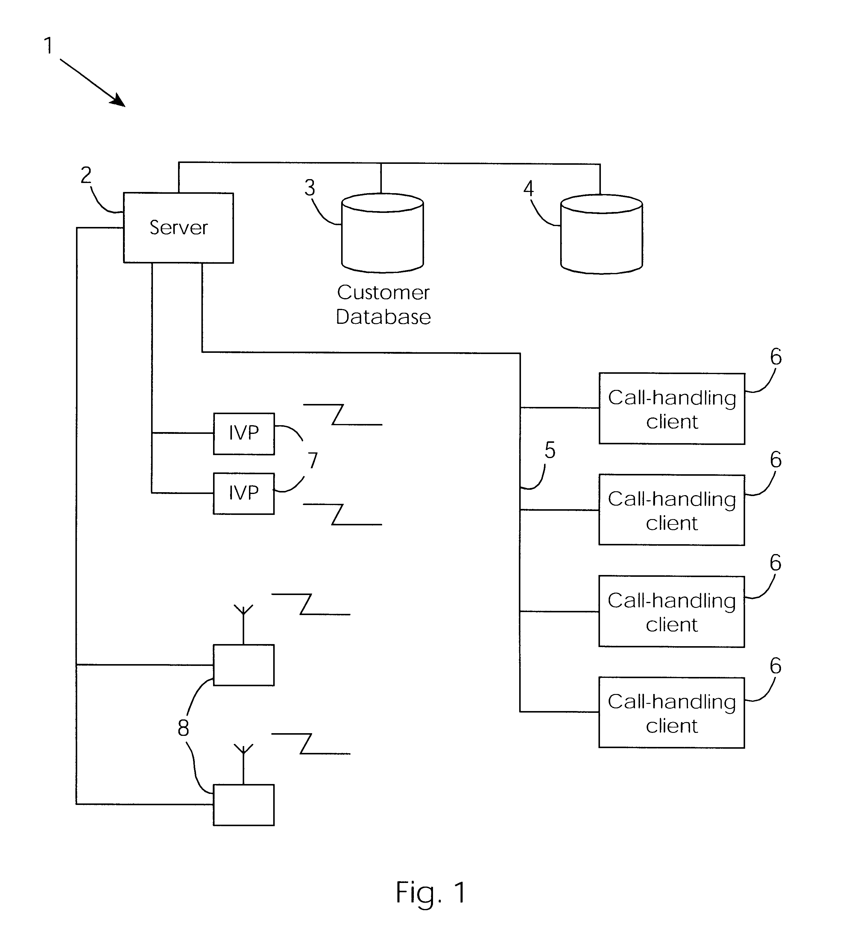
Referring initially to FIG. 1, a cable network repair control system 1 of the invention is illustrated. The system 1 comprises a server 2 which is connected to a customer database 3 and to a database 4 of repair control tables. These databases are typically many Giga bytes in size as they are required to have data relating to at least 100,000 customers and in some instances a number which is orders of magnitude greater. The server 2 is connected by a network 5 to call handling clients 6 which are used by personnel in a call centre for taking trouble calls from customers and accessing the server 2. Interactive voice processors 7 are connected to the server 2 on one side and to a telephone network on the other. Finally, the server 2 comprises radio transmitters / receivers 8 for wireless communication.

The databases 3 and 4 have approximately 250 tables which are highly integrated with referential integrity.

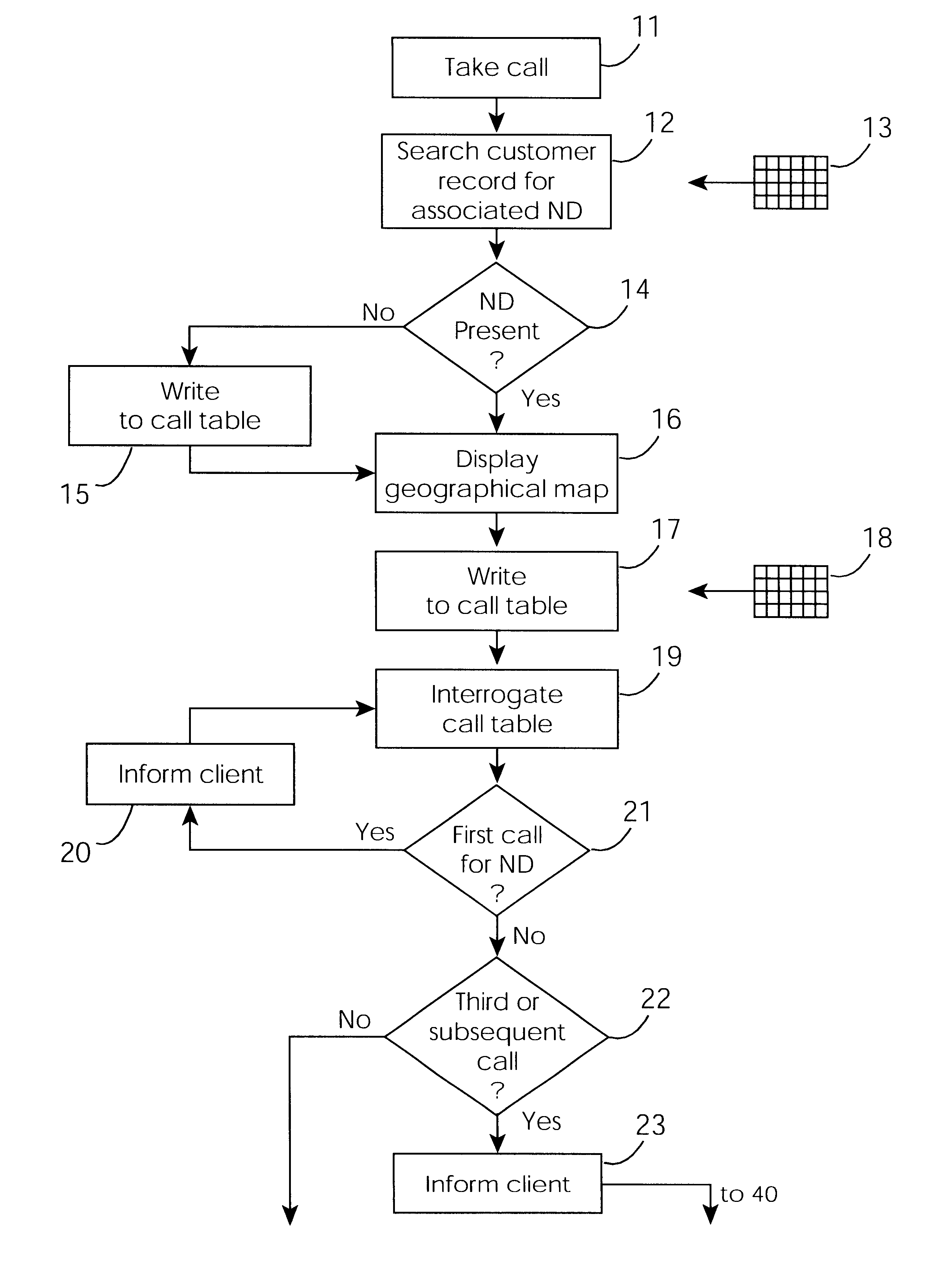
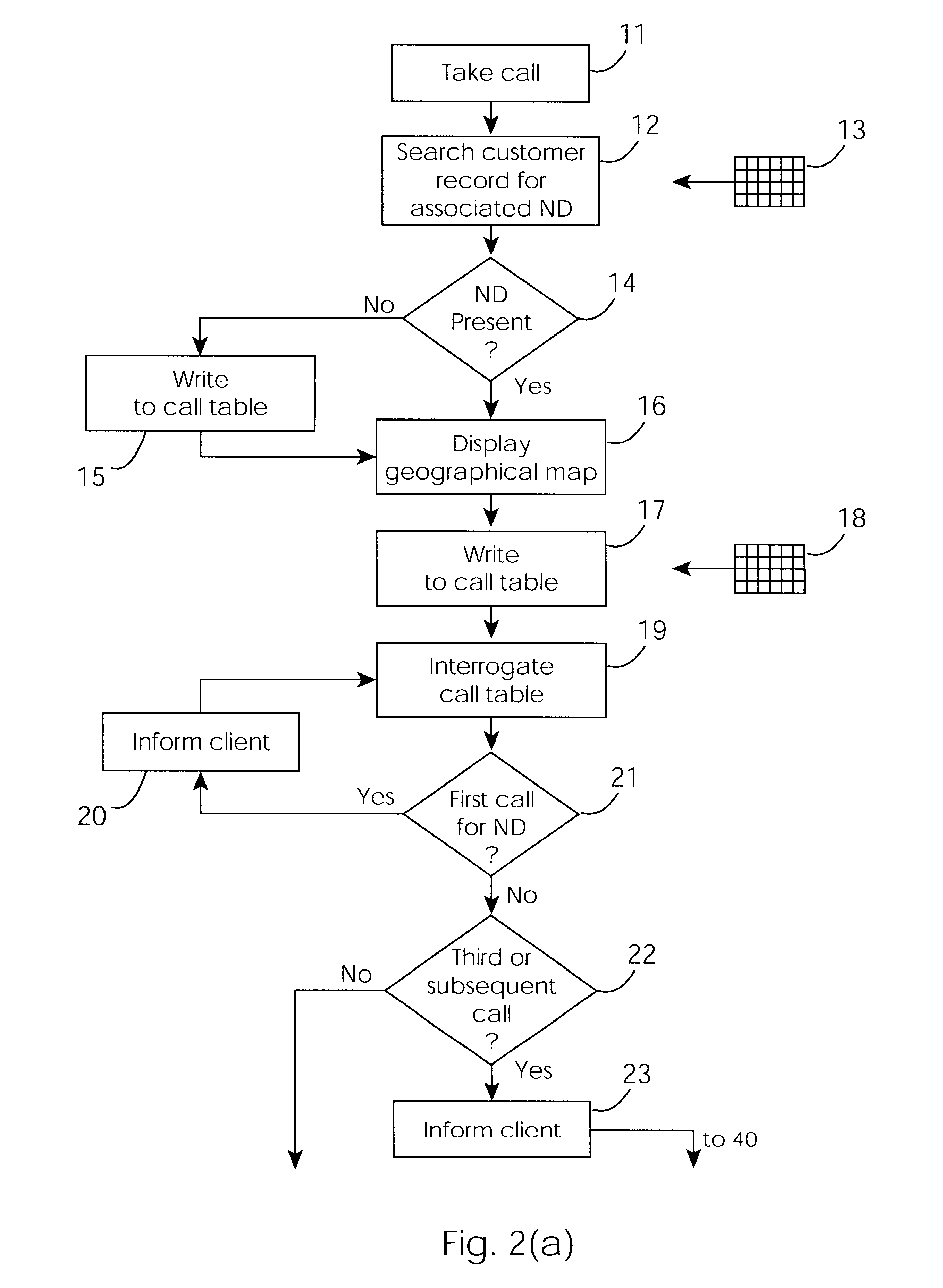
Referring now to the remaining drawings, an overall method of operation of the sy...


PUM


Abstract

A cable network repair control system including a server communicating with multiple call-handling clients in a trouble call center. The databases are used to automatically determine an associated network device for the customer who makes a trouble call. When a second call is received for a particular network device, an inferencing engine automatically operates to identify potential repairs crews and to control communication with them to ensure that optimum use of the repair crew time and quick repair. Various tables are generated dynamically and are used to update management status tables for reviewing of network repair status.

Description

The invention relates to a cable network repair control system comprising means for receiving data arising from trouble calls reporting faults in a cable network system such as an electrical distribution system.PRIOR ART DISCUSSIONHeretofore, such systems have been quite passive in their operation and there has been little integration with the network itself and with resources for repairing the faults which arise.OBJECTS OF THE INVENTIONIt is therefore an object of the invention to provide a cable network repair control system which allows trouble calls to be taken and to be analysed.Another object is that the system assists with location of faults to reduce the average time between taking a trouble call and the fault being repaired.A still further object is that the system provide for tracking and management of field resources.According to the invention, there is provided a cable network repair control system comprising a data storage device, a processor, and a plurality of trouble...

Claims


Application Information

Patent Timeline
Patent Type & Authority Patents(United States)
IPC IPC(8): G06F11/00G06F11/07H04L12/24
CPCG06F11/0748H04L43/0811G06F11/0793H04L41/06
Inventor HYLAND, JAMESHYLAND, EILEEN
Owner LAKEFIELD ETECH GROUP
Why Eureka
Try Eureka