Image forming apparatus and sheet feeder

a technology of image forming apparatus and feeder, which is applied in the direction of electrographic process apparatus, thin material processing, instruments, etc., can solve the problems of difficulty in applying type of technique, impaired degree of freedom in the configuration or layout of the image forming engine inside the printer unit, and complicated operation correspondingly

Inactive Publication Date: 2004-01-06
FUJIFILM BUSINESS INNOVATION CORP
View PDF12 Cites 82 Cited by
  • Summary
  • Abstract
  • Description
  • Claims
  • Application Information

AI Technical Summary

Benefits of technology

]As described above, in accordance with the invention, since the recording-material discharging section is disposed above the image forming section, the recording-material supplying section is disposed below the image forming section, and the rear-side transporting path is provided in a portion of the transporting paths of the recording material, it is possible to provide an image forming apparatus requiring only a small installation area without securing a wasteful space for clearing a jam.Further, as described above, in accordance with the invention, since the sheet feeding member provided on the innermost recess side of the sheet tray is arranged to be pulled out toward this side of the apparatus in interlocking relation to the sheet tray, both the loading of the sheets and the clearing of jams can be effected from this side of the apparatus. Therefore, it is possible to easily remove the jammed sheet without causing a decline in the substantial space efficiency.

Problems solved by technology

With such a printer, since the replacement of the paper feeding tray is required in correspondence with the print size, there is a problem in that the operation becomes complicated correspondingly.
However, due to the limitations imposed on the transporting paths of the recording material, the degree of freedom in the configuration or layout of the image forming engine inside the printer unit is impaired.
Therefore, there is a technical problem in that the installation space of the image forming apparatus must be made wider on the rear side than the area occupied by the image forming apparatus by the portion required for opening or closing the rear cover.
Hence, this type of technique is difficult to apply to a mode in which the recording material cassette is accommodated in the apparatus body such that the user operation-side surface of the recording material cassette becomes substantially flush with the surface of the apparatus body.
For this reason, when the recording material is jammed in the rear-side transporting path, even if the user, after pulling out the recording material cassette, tries to clear the jam by making use of the space from which the recording material cassette was pulled out, the user's hand does not reach the rear-side transporting path, and the clearing of the jam is extremely difficult.
Further, with the above-described paper feeding unit, paper jams can occur during the transport of the paper.
Therefore, there has been a technical problem in that a substantial occupying area becomes large correspondingly, so that the space efficiency declines.

Method used


Image

  • Image forming apparatus and sheet feeder
  • Image forming apparatus and sheet feeder
  • Image forming apparatus and sheet feeder

Examples


first embodiment

(First Embodiment)

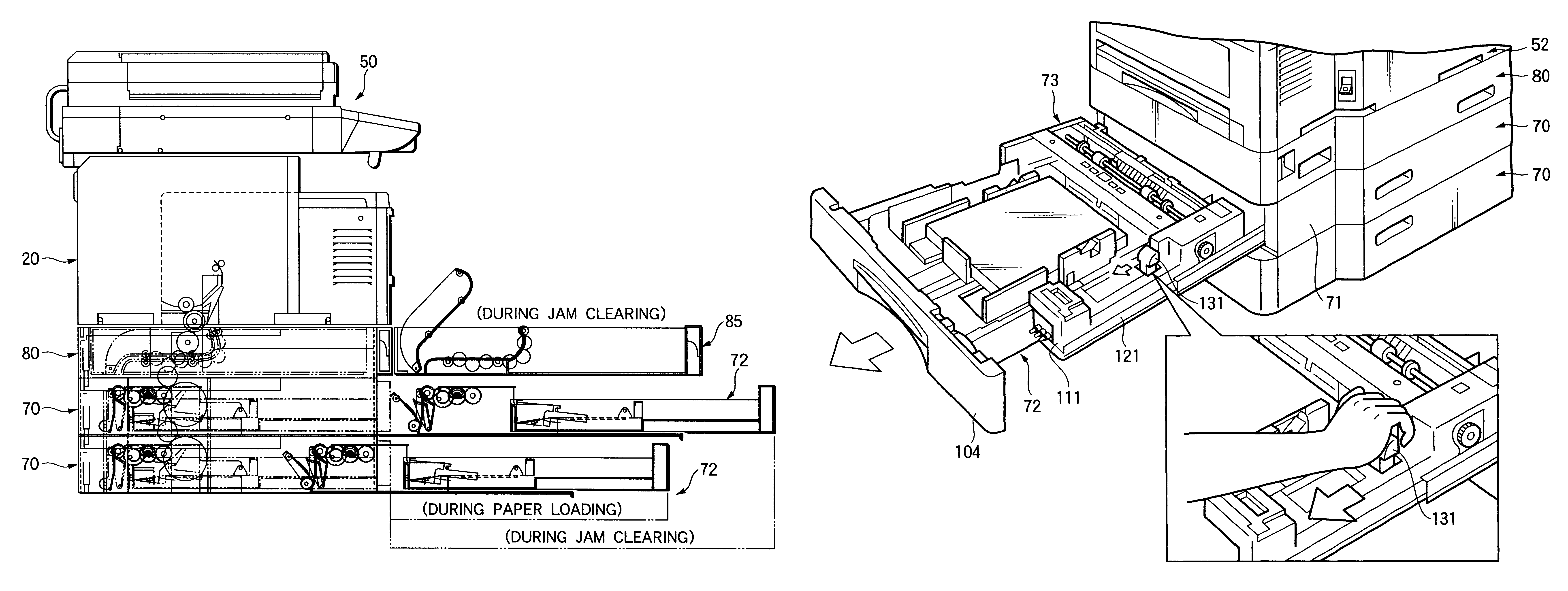
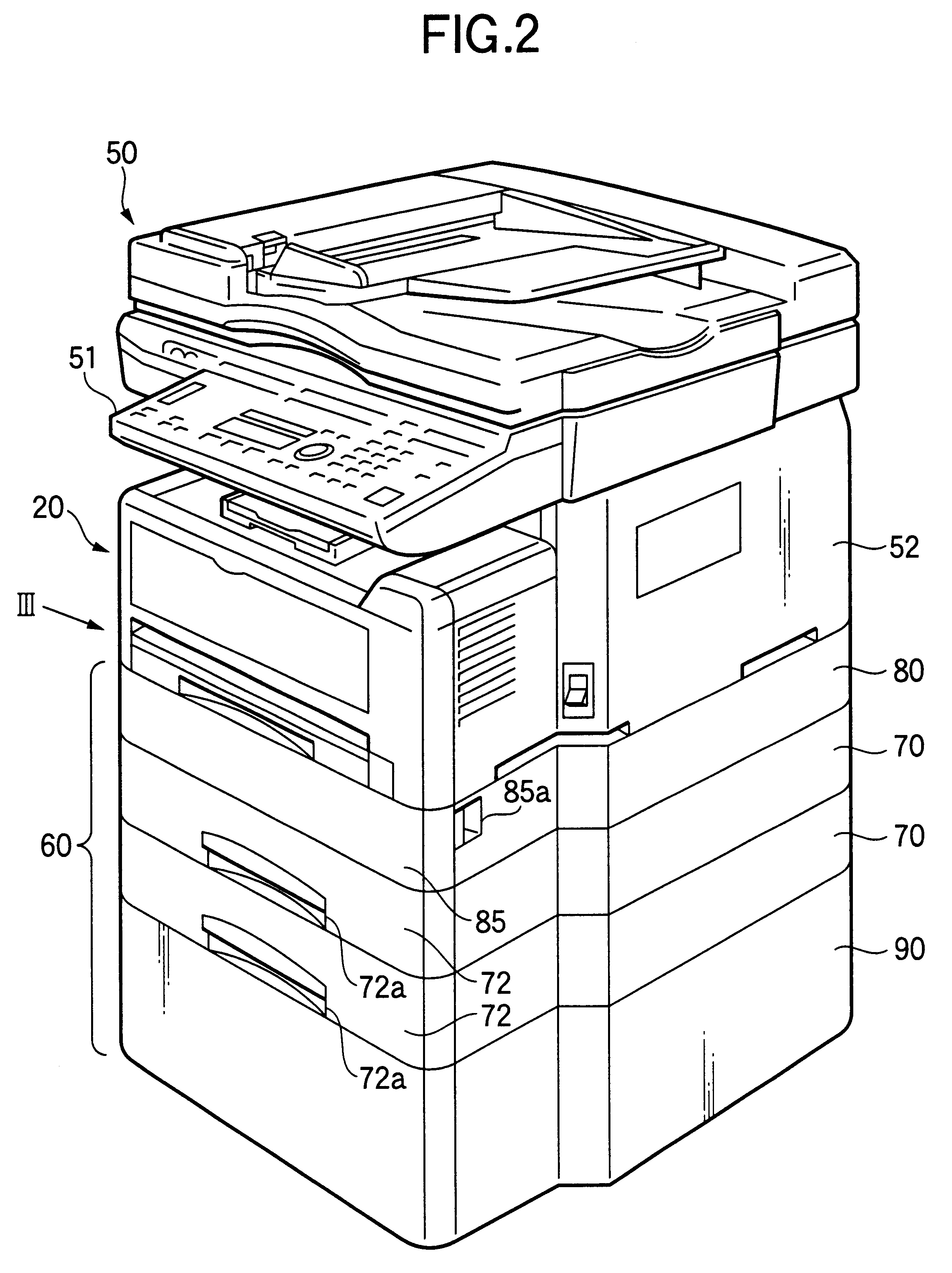
FIGS. 2 to 4 are explanatory diagrams illustrating a first embodiment of an image forming apparatus to which the invention is applied.

This image forming apparatus is a so-called combination machine having the respective functions of a copying machine, a facsimile machine, a printer, and a scanner.

In the drawing, the image forming apparatus in accordance with this embodiment is provided with a printer unit 20 incorporating a process cartridge for image formation, an image reading unit 50 disposed on top of the printer unit 20, and paper feeding units 70 disposed below the printer unit 20 and adapted to feed paper serving as a recording material to the printer unit 20. Further, an operation panel 51 is provided on this side of the image reading unit 50.

It should be noted that, in FIGS. 2 to 4, reference numeral 90 denotes a stand which is disposed underneath the lowest paper feeding unit 70 for adjusting the height of the image forming apparatus.

In this embodiment, t...

second embodiment

(Second Embodiment)

Although this embodiment is substantially similar to the first embodiment, the intermediate transport unit 80 is further provided with a paper feeding cassette 91, as shown in FIG. 21.

It should be noted that, of the constituent elements of the image forming apparatus in accordance with this embodiment, those which are similar to those of the image forming apparatus in accordance with the first embodiment will be denoted by the same reference numerals, and a detailed description thereof will be omitted here.

Paper of the same size as that in the paper tray 32 of the printer unit 20 or paper of a smaller size is accommodated in the paper feeding cassette 91 so that the paper feeding cassette 91 will not cause a hindrance to the paper transporting passage 81.

In addition, a paper feed roll 92 is disposed on the innermost recess side of the paper feeding cassette 91 so as to feed out the paper toward the paper transporting passage 81.

In addition, since the paper feeding...

third embodiment

(Third Embodiment)

FIG. 22 is a schematic diagram illustrating an outline of the image forming apparatus in accordance with a third embodiment.

In this embodiment, in the same way as the first embodiment, to make it possible to accommodate paper larger than the paper accommodated in the paper tray 32 of the printer unit 20, the depth of the paper feeding units 70 is set to be larger than the depth of the printer unit 20.

However, in this embodiment, unlike the first embodiment, the printer unit 20 is disposed in such a manner as to offset on the opposite side of the operation panel 51 side (this side) of the image forming apparatus, and the rear-side paper transporting passages of the paper feeding units 70 and the paper transporting passage of the printer unit 20 are arranged in a substantially rectilinearly communicating manner.

In this mode, since a space is provided on this side of the printer unit 20, to keep the appearance attractive a dummy cover 600 is provided on this side of t...


PUM


Abstract

An image forming apparatus and sheet feeder in which a recording-material transporting system is provided for transporting to an image forming section recording material supplied from a recording-material supplying section and for subsequently guiding the recording material to a recording-material discharging section. A portion of the transporting path is arranged on a rear side of the apparatus body located on an opposite side to the user operation side. At least either one of the recording-material supplying section and the recording-material transporting system is provided with a jam clearing section for allowing recording material jammed in the recording-material transporting system to be both accessed from and cleared on the user operation side without need to open any access panels on the side portions or rear portion of the apparatus body. As a result the apparatus may be located without reserving space for opening a side or rear access portion.

Description

1. Technical FieldThe present invention relates to an image forming apparatus such a printer, a copying machine, and a facsimile machine, and more particularly to improvements of an image forming apparatus in which a rear-side transporting path is included as at least a portion of recording-material transporting paths.Further, the present invention relates to a sheet feeder for use in such as a printer, a copying machine, and a facsimile machine, and more particularly to improvements of a sheet feeder of the type in which sheets are fed from the innermost recess side of a sheet tray in the inserting direction thereof, the sheet tray being disposed in such a manner as to be capable of being inserted or pulled out. The sheet used in the present invention has a size in a range of a size from a postcard to the JIS standard A3 size for a machine drawing including a legal size.2. Related ArtAs a conventional image forming apparatus of this type, one is already known which is comprised of ...

Claims


Application Information

Patent Timeline
Patent Type & Authority Patents(United States)
IPC IPC(8): G03G15/00G03G21/16
CPCG03G15/6502G03G21/1638B65H2601/11G03G2215/00544G03G2221/1675G03G2221/1684G03G15/00
Inventor ENOMOTO, KAZUOIIHARA, KAZUHIROMISU, TOSHIAKINISHIMURA, MASAKUNI
Owner FUJIFILM BUSINESS INNOVATION CORP
Why Eureka
Try Eureka