
Insertion of scan hardware

a scan hardware and hardware technology, applied in the field of integrated circuits, can solve the problems of not being able to automatically insert scan cells into circuits, the job of designing electronic circuits has also grown correspondingly more difficult, and the current eda tools suffer from many shortcomings

Inactive Publication Date: 2004-01-06
GLOBALFOUNDRIES INC
View PDF4 Cites 36 Cited by
  • Summary
  • Abstract
  • Description
  • Claims
  • Application Information

AI Technical Summary

Benefits of technology

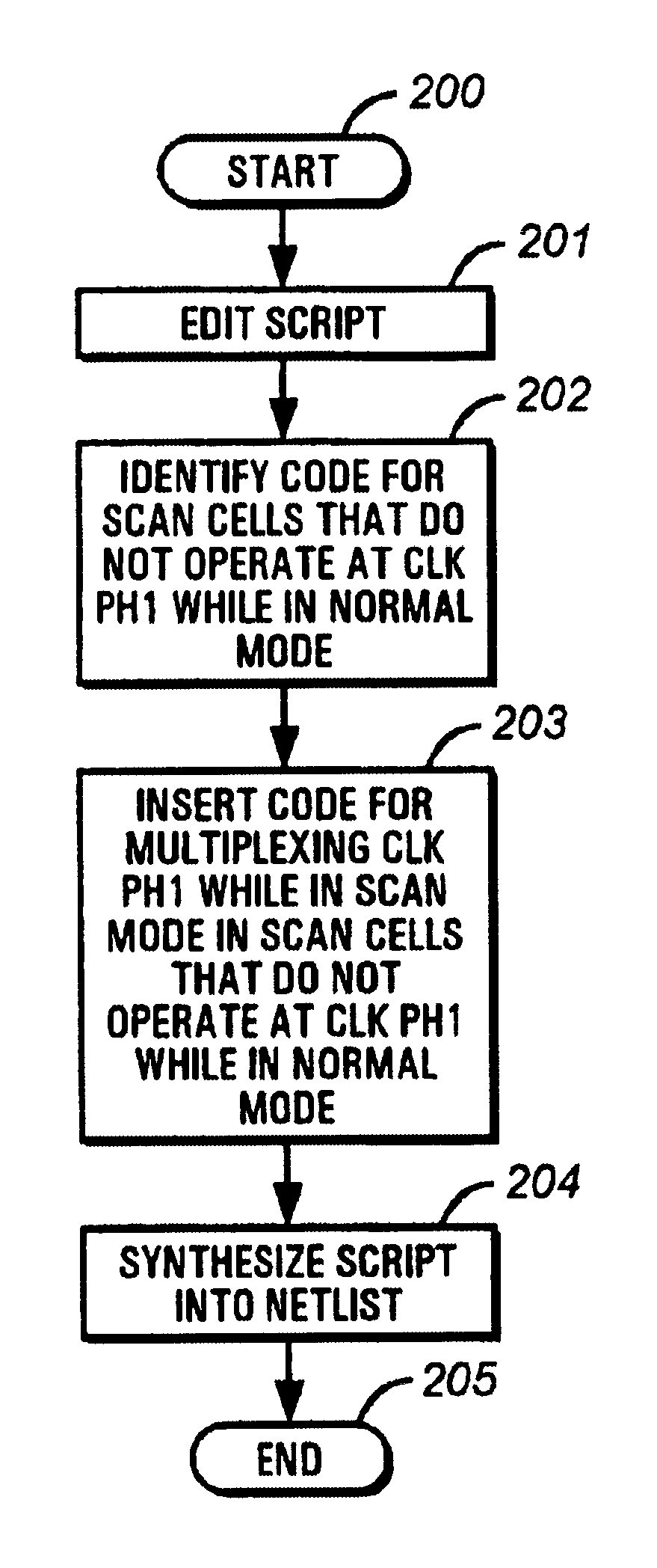
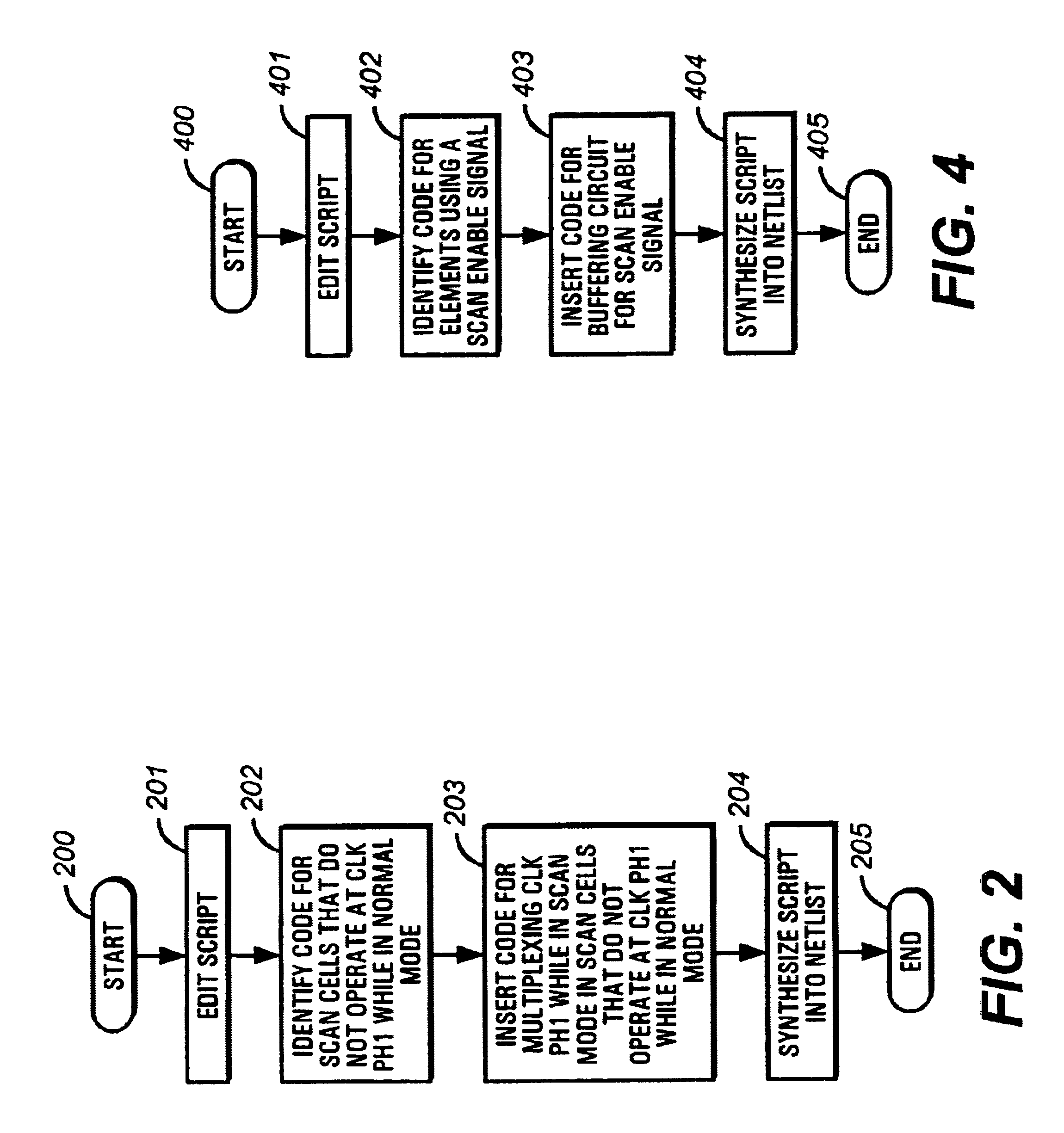
The present invention relates to a method for automatically inserting scan cells into integrated circuits, such as microcontrollers, using a high-level language script. The method addresses the shortcomings of current electronic design automation (EDA) tools, which cannot automatically insert scan cells into circuits that utilize multiple clocks, do not take into account the drivers needed for complex scan chains, and cannot be used to automatically insert scanned cells into ICs that include legacy cores. The invention provides a solution for incorporating multiplexers in a scan chain and drivers for a scan cell, as well as a fake clock to force the EDA tool to have different scan chains for each clock domain. The technical effect of the invention is to improve the efficiency and accuracy of designing complex integrated circuits.

Problems solved by technology

Naturally, the job of designing these electronic circuits has also grown correspondingly more difficult.
However, current EDA tools suffer from many shortcomings.
First, the EDA tools generally cannot automatically insert scan cells into circuits that utilize multiple clocks.
Timing conflicts result in the scan chain when scan cells operate at different frequencies.
In addition, due to the size and complexity of scan chain, current EDA tools do not take into account the drivers needed for the complex scan chain.
Furthermore, EDA tools generally cannot be used to automatically insert scanned cells into ICs that include legacy cores.
When an IC is in the scan mode, the outputs of the legacy cores are not taken into account, resulting in erroneous test data.
Current EDA tools suffer from many short comings that affect design and manufacture of integrated circuits, such as microcontrollers.
Signals from the legacy core generally have little controllability since it comes from a legacy core without scan or other recent test ability techniques.

Method used


Image

  • Insertion of scan hardware
  • Insertion of scan hardware
  • Insertion of scan hardware

Examples


Embodiment Construction

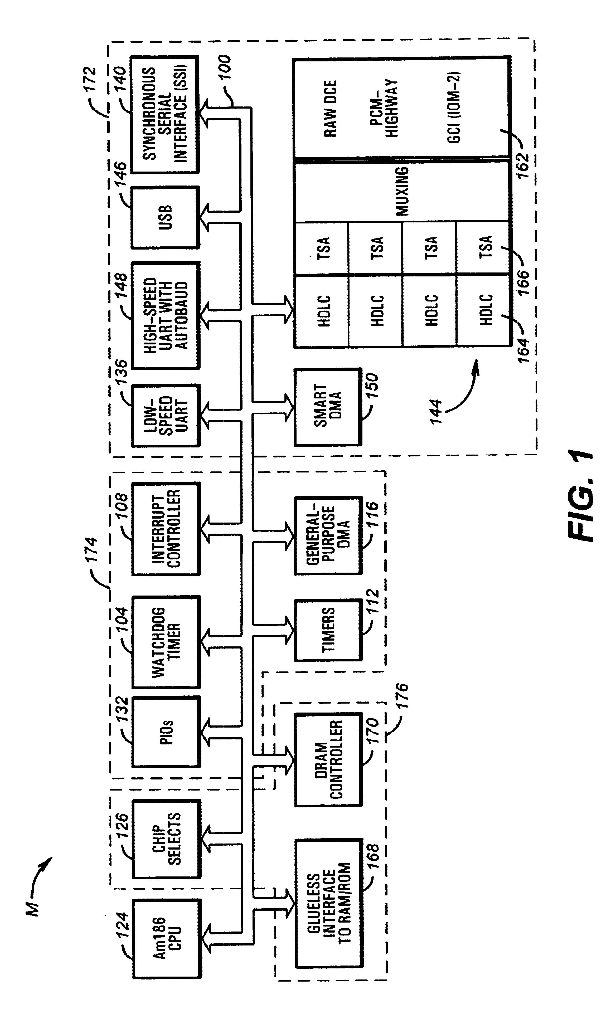
Turning to FIG. 1, shown is a block diagram of a typical microcontroller M that could be evaluated using a logic system according to the invention. Such a microcontroller is preferably implemented on a single monolithic integrated circuit.

The microcontroller M preferably includes an internal bus 100 coupling, an execution unit 124, system peripherals 174, memory peripherals 176 and serial communication peripherals 172. The execution unit 124 in the disclosed embodiment is compatible with the AM186 instruction set implemented in a variety of microcontrollers from Advanced Micro Devices, Inc., of Sunnyvale, Calif. A variety of other execution units could be used instead of the execution unit 124. The system peripherals 174 include a watch dog timer (WDT) 104 for generating non-maskable interrupts (NMIs), microcontroller resets, and system resets. An interrupt controller 108 for supporting thirty-six maskable interrupt sources through the use of fifteen channels is also provided as a s...


PUM


Abstract

According to the present invention, a method for inserting scan hardware into Integrated Circuits (IC) such as microcontrollers is disclosed. Custom scripts used by electronic design automation (EDA) tools are configured to accommodate those microcontroller designs that operate with multiple clocks and legacy cores. Furthermore, according to the present invention, custom script are used to provide buffering circuits to drive the scan hardware.

Description

1. Field of the InventionThe present invention relates to integrated circuits (IC), more particularly to insertion of scan hardware using electronic design automation (EDA) tools.2. Description of the Related ArtWith regularity over the past years, integrated circuits (IC) such as microcontrollers have gotten smaller, yet in the meanwhile have become more powerful. Today, it is not uncommon for a microcontroller to contain millions of transistors. Naturally, the job of designing these electronic circuits has also grown correspondingly more difficult. What was once accomplished by a single designer or a small group of designers, the job of designing microcontrollers must now be typically performed by a large team of designers or multiple teams of designers.Specialized microcontrollers with integrated communication features are becoming particularly attractive for communication applications. A microcontroller, or an embedded controller, is uniquely suited to combining functionality on...

Claims


Application Information

Patent Timeline
Patent Type & Authority Patents(United States)
IPC IPC(8): G01R31/3185G01R31/3183G01R31/28
CPCG01R31/318342G01R31/318552G01R31/318594
Inventor BASTO, LUIS A.FOX, MARK T.
Owner GLOBALFOUNDRIES INC
Learn More