Ball tap with a water level switch

a technology of water level switch and ball tap, which is applied in the direction of valve operating means/release devices, machines/engines, instruments, etc., can solve the problems of float switch, two floats, and may interfere with each other, and can be a significant obstacl

Inactive Publication Date: 2004-01-20
YOSHITAKE INC
View PDF30 Cites 23 Cited by
  • Summary
  • Abstract
  • Description
  • Claims
  • Application Information

AI Technical Summary

Problems solved by technology

Accordingly, if the horizontal sectional area of the tank is rather small, the two floats, one of the ball tap and the other of the float switch, may interfere with each other.
This generally becomes a significant obstacle for an appropriate arrangement of the ball tap and the float switch in the same tank.

Method used


Image

  • Ball tap with a water level switch
  • Ball tap with a water level switch
  • Ball tap with a water level switch

Examples


Embodiment Construction

An embodiment of this invention is explained below with reference to accompanying drawings.

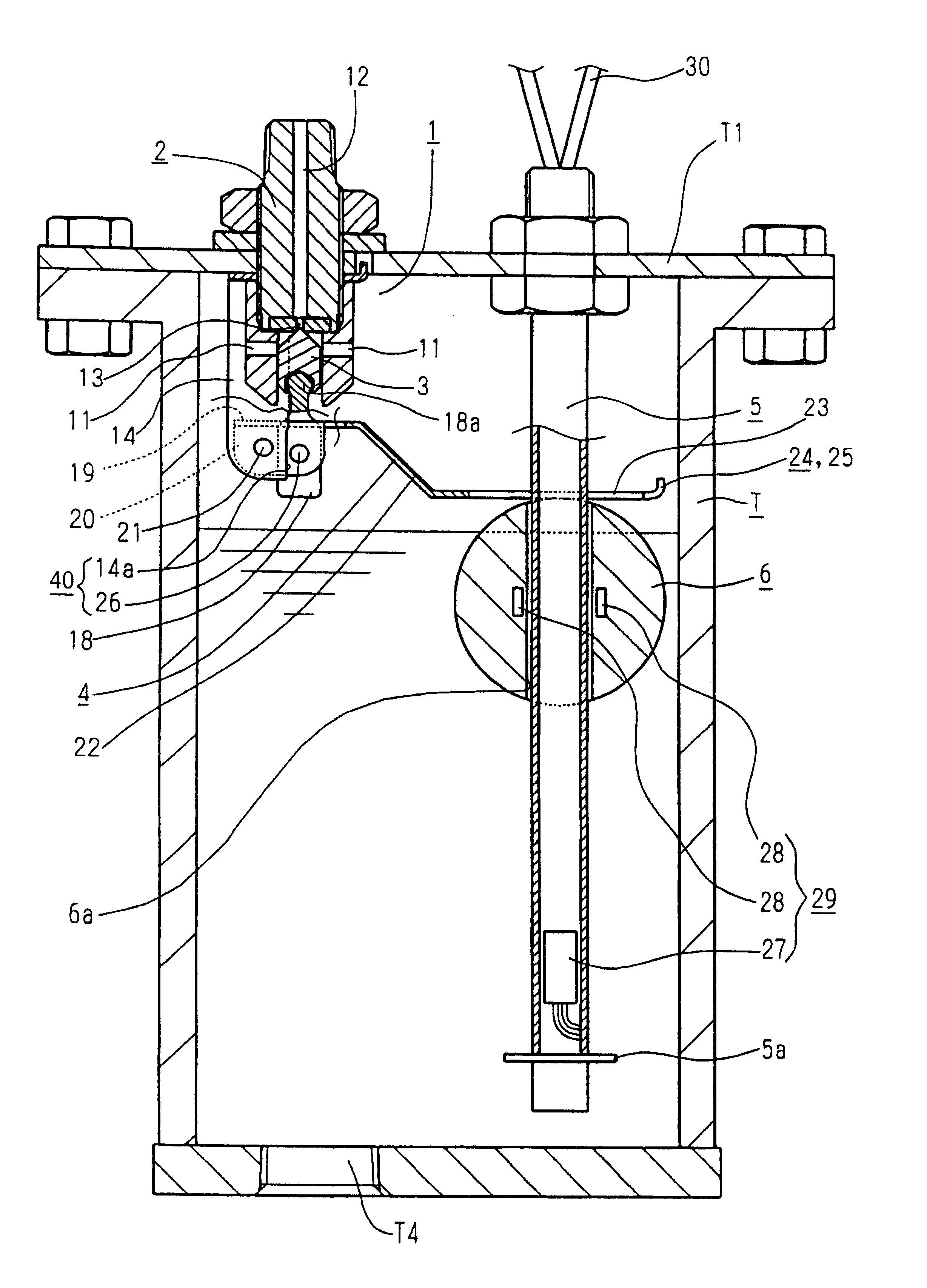
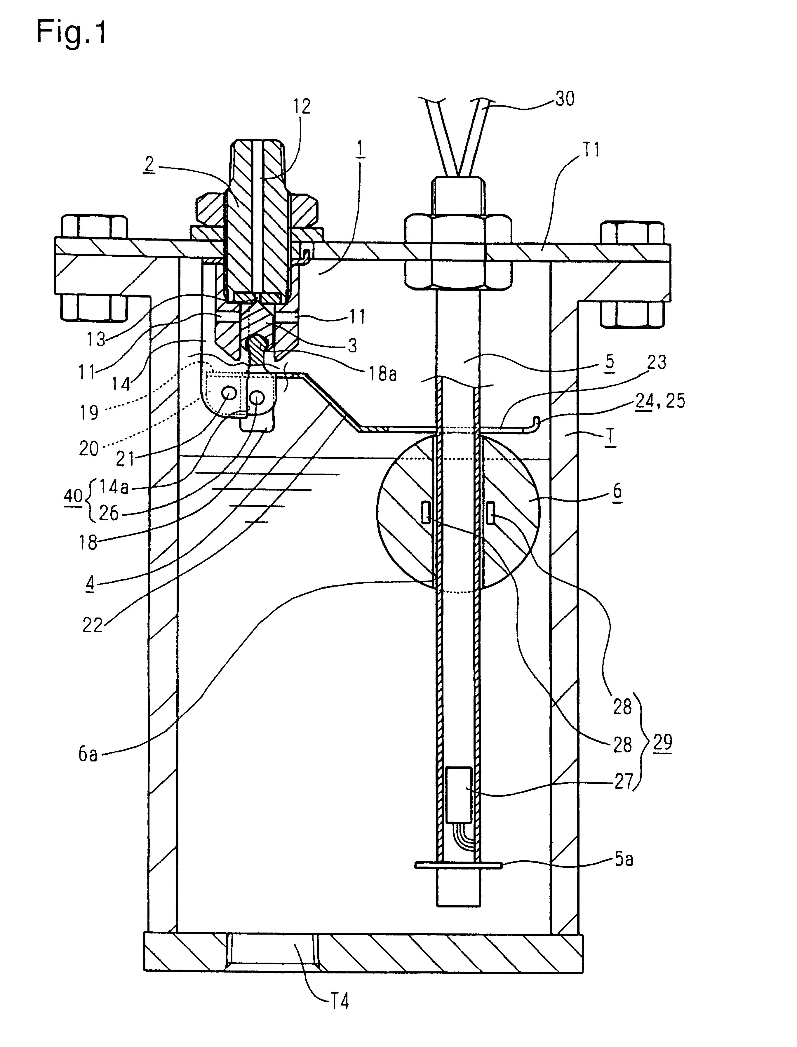
A ball tap 1 of FIG. 1 mainly comprises a valve body 2 mounted on a ceiling T1 of a tank T, a lever 4 operating a valve 3 built in the valve body 2, a guide standpipe 5 perpendicularly extending within the tank T, and a float 6 freely slidable and axially mounted on the guide standpipe 5 and linked with the lever 4.

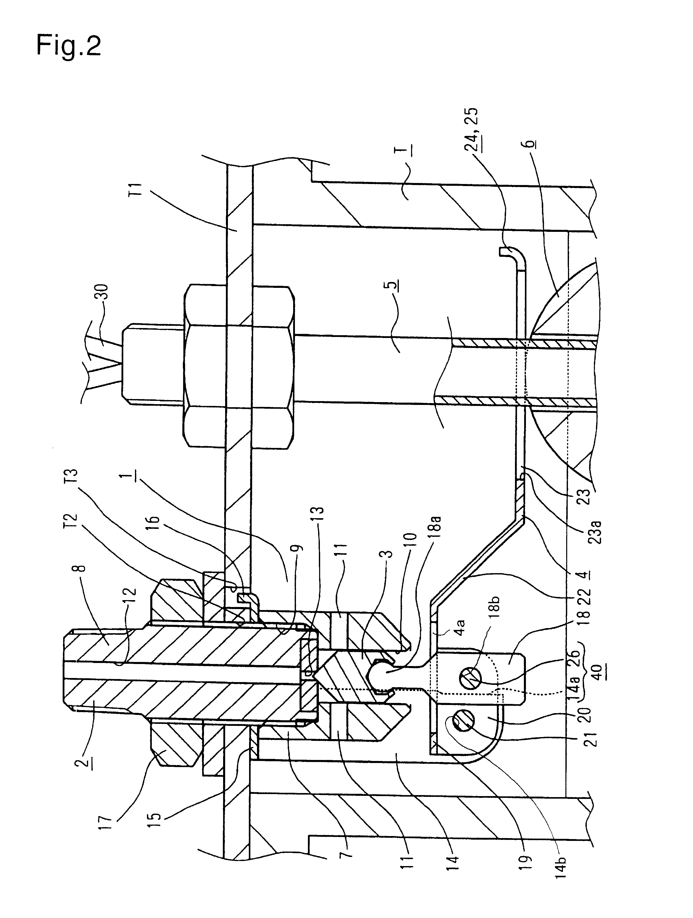
The valve body 2 comprises a cylindrical valve guard 7, having a groove that appears rectangular in the cross-sectional view, and a vertical valve bolt 8, where the diameter of the valve bolt 8 is smaller than that of the cylindrical valve guard 7, such that the valve bolt 8 is capable of being screwed in to and out from the cylindrical valve guard 7.

The cylindrical valve guard 7 has an internal thread 9, formed between its upper and intermediate portions, to screw a lower end of the vertical valve bolt 8 therein. The cylindrical valve guard 7 also has a valve guide bore 10, a diame...


PUM


Abstract

A compact ball tap with 1 a water level switch which comprises a guide standpipe 5 vertically arranged in a tank T, a float 6 slidably installed on the guide standpipe 5, a valve 3, a lever 4 controlling an open-close action of the valve 3 connected with the float 6, and a water level switch 29 transmitting predetermined control signals when the float 6 shifts to a predetermined water level, wherein one float 6 is shared by the ball tap 1 and the water level switch 29.

Description

This invention relates to a ball tap with a water level switch installed therein.DESCRIPTION OF THE PRIOR ARTA conventional water supply system has a tank generally comprising a ball tap and a float switch.The ball tap is configured such that a lever extending therefrom ramps downward to reach a float formed thereon. The float makes a vertical movement along the lever swing in response to the changing water level within a tank. The vertical motion of the float automatically regulates the water level by means of feeding or suspension of water feeding so as to maintain a predetermined water level within the tank.The float switch system is sensing system. At a predetermined water level within the tank a switch is activated by another float due to the float's vertical movement within the tank in response to the changing water level within the tank. Upon reaching the predetermined water level another device, such as an alarm unit and / or an indicating lamp, connected to the float switch, ...

Claims


Application Information

Patent Timeline
Patent Type & Authority Patents(United States)
IPC IPC(8): F16K21/00F16K31/18F16K31/24F16K33/00F16K21/18G01F23/30G01F23/74E03D1/33
CPCF16K21/185F16K31/24F16K33/00G01F23/74Y10T137/7423Y10T137/7439Y10T137/7465Y10T137/8342
Inventor KATO, NOBUHIDEMIZUNO, HIROYUKI
Owner YOSHITAKE INC
Why Eureka
Try Eureka