Discharge cap for releasable product
a technology for releasable products and discharge caps, which is applied in the direction of liquid dispensing, containers, bottles, etc., can solve the problems of awkward overall height of the cap above the container, complex design and die needed for the manufacture of the neck portion, etc., and achieve the effect of dissolving quickly
- Summary
- Abstract
- Description
- Claims
- Application Information
AI Technical Summary
Benefits of technology
Problems solved by technology
Method used
Image

Examples
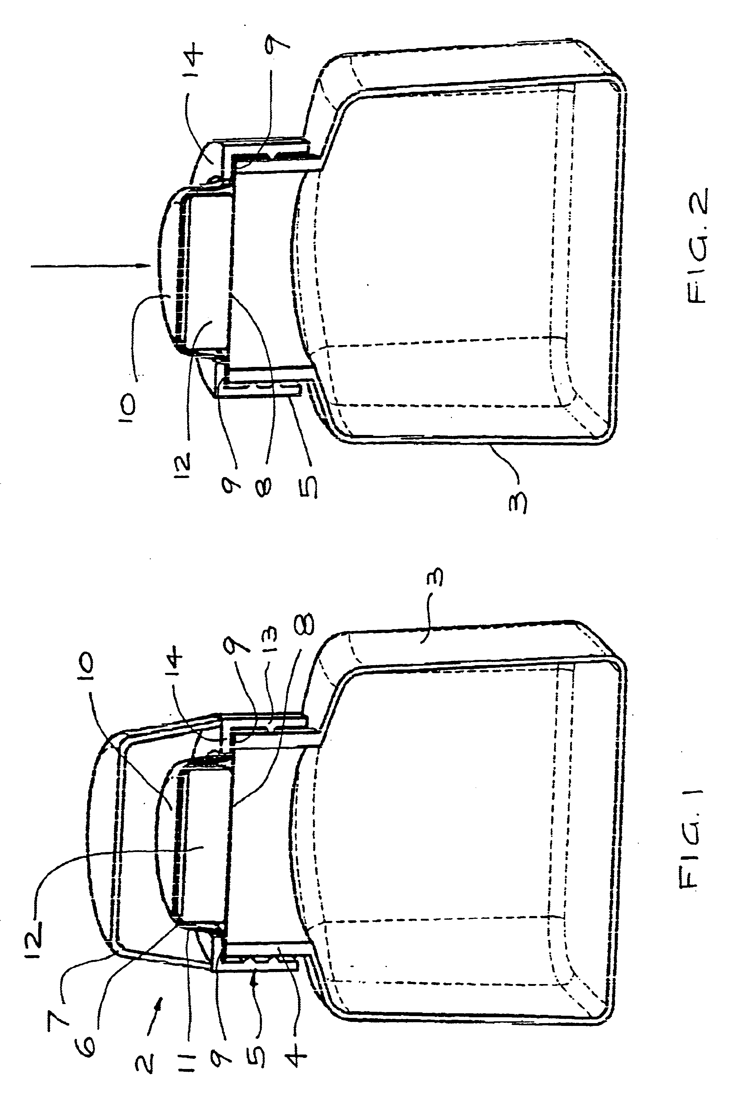
first embodiment
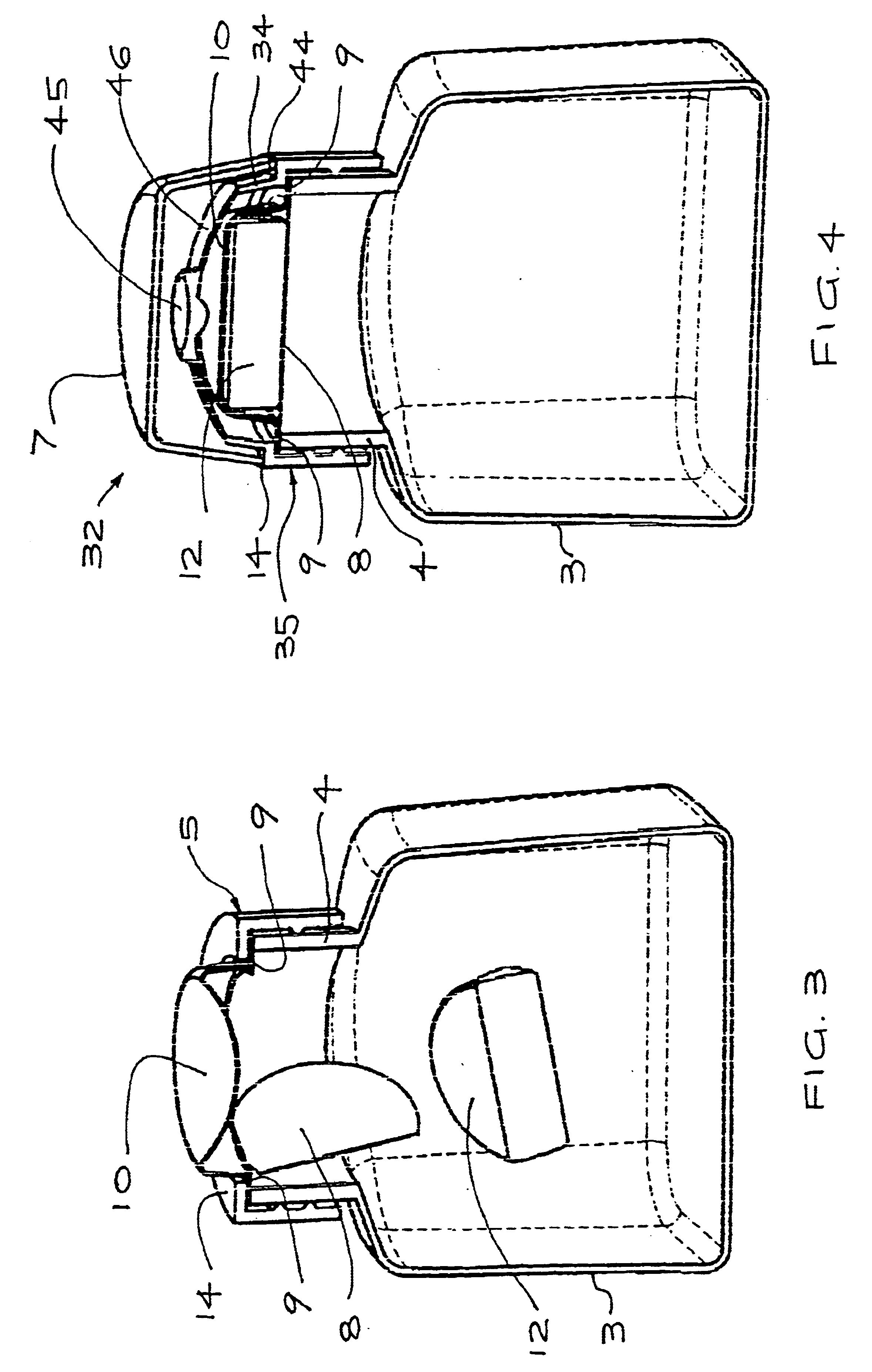
The collar 35 includes a flange 44 and upper sloping side 34 to a domed top 46. At the centre of the top 46 is a button 45. The collar 35 is formed integrally. The flange 44 performs the same function as the flange 14 of the first embodiment, as described above.
To mix the two parts of the drink, the cover 7 is removed and downward force exerted on the button 45 (FIG. 5). This downward pressure is generally supplied by a thumb or other manual means. The lesser burst strength of the base 8 causes this to break before the top 10. The flange 44 retains the edge 9 in position. Thus after the base 8 has broken, the tablet 12 is forced or dropped into the container 3, mixing with the liquid therein (FIG. 5).
The container 3 can be shaken or moved to aid in the mixing of the tablet 12 into the liquid. The liquid seal is provided by the edge 9 and the top 10 of the tablet holder 6, which is retained in position by the collar 35. Once the tablet is completely dissolved, the collar 35 and the r...
fourth embodiment
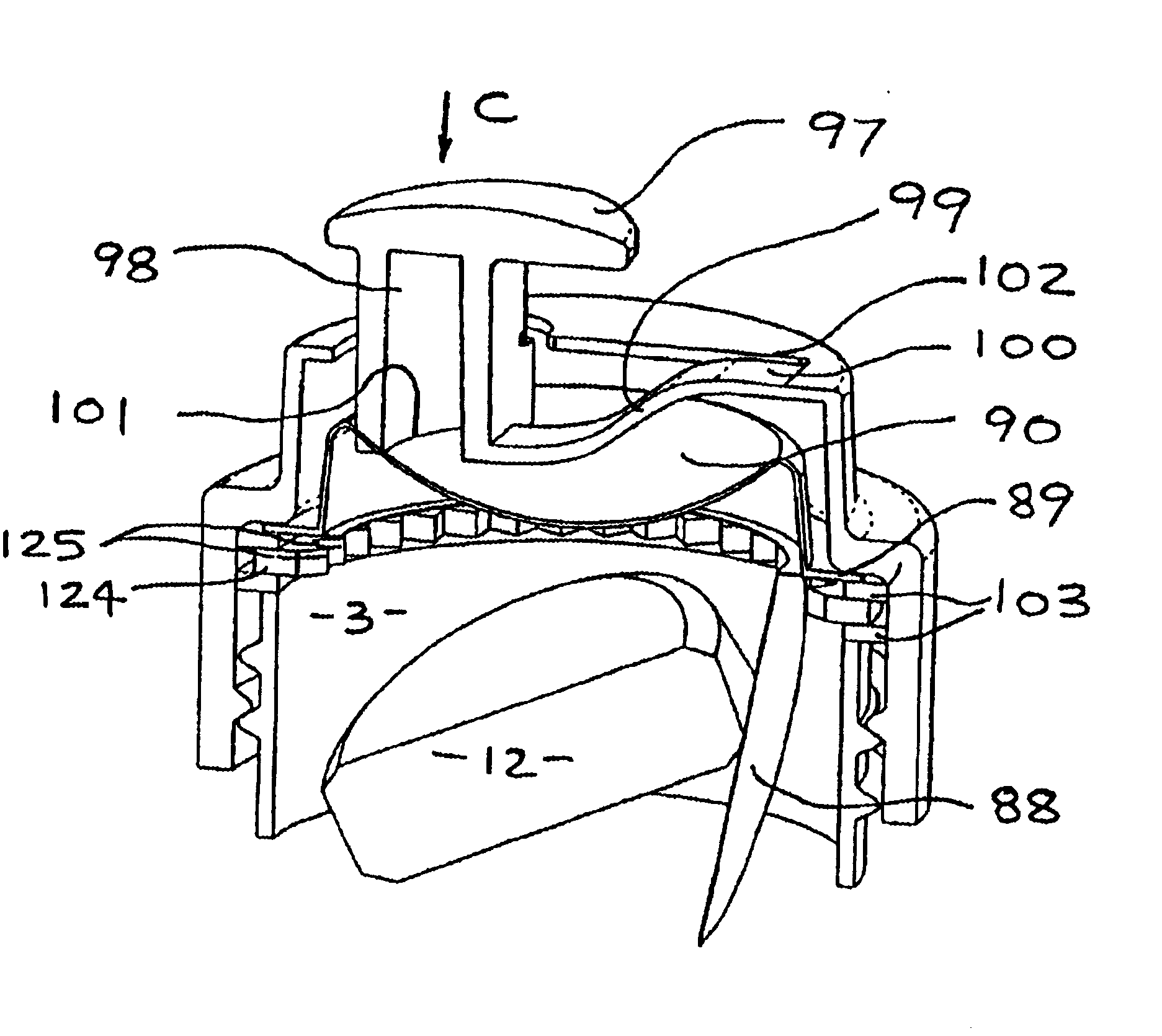
Referring to FIG. 11, a fifth preferred embodiment of the cap 112 of the present invention is thereshown. Where parts are unchanged from that discussed above with reference to the fourth embodiment, like numerals are used.
Referring to FIGS. 11 and 21(a,b), the collar 105 includes a first preferred embodiment of an annular cutting ring 424. The ring 424 includes a plurality of teeth 425 or saw edgings, giving the ring 424 a saw-tooth appearance. The tips of the teeth 425 are positioned on a circumference which is substantially the same as the circumference of the weakened area B on the tablet holder 106, if the second preferred embodiment of the holder 106 is used. If so desired, the teeth 425 continue around all the circumference of the ring 424. The collar 105 also includes two seals 103, one above and one below the cutting ring 424.
The operation of the collar 105 has only minor variations on that of the first preferred embodiment of the collar 85, except that as the base 101 bears...
second embodiment
Referring to FIGS. 8a and b, the cutting ring 224 is thereshown. The inner tip 225 of the ring 224 is a continuous tapered tip around the circumference of the ring 224.
FIGS. 19a and b show a third preferred embodiment of a cutting ring 324 of the present invention, in which the inner, upper corner 325 of the ring 324 acts as the cutting edge. In like manner, FIGS. 21a and b show a fourth preferred embodiment of the cutting ring 424 with teeth 425. The major difference between this embodiment and the fourth preferred embodiment of the ring 124 is that the teeth 425 do not taper to a point at the tip as do the teeth 125 (FIGS. 17a and b).
Referring to FIG. 12, a third preferred embodiment of the collar 205 is thereshown in a sixth preferred embodiment of the cap 132 of the present invention. Where parts are unchanged from that discussed above with reference to the fourth embodiment, like numerals are used.
The collar 205 includes a cutting ring 124 and one seal 103. Whilst the ring 124 ...
PUM
 Abstract
Description
Claims
Application Information