Connector for a flexible circuit board

a flexible circuit board and connector technology, applied in the direction of heat measurement, coupling device connection, instruments, etc., can solve the problems of inability to ensure a reliable electric connection, inability to ensure the retention of flexible circuit boards on target positions, and undesirable displacement of flexible boards

Inactive Publication Date: 2004-01-20
JST MFG CO LTD
View PDF4 Cites 27 Cited by
  • Summary
  • Abstract
  • Description
  • Claims
  • Application Information

AI Technical Summary

Benefits of technology

The resilient supports may be of such a shape that they engage with apertures or cutouts formed in the inner end portion of said flexible board being inserted. In this case, the flexible board will more surely be protected from its slipping off and displacement on one hand, and any excessively strong pulling force or the like external force possibly imparted to the flexible board will cause an elastic deformation of the said supports on the other hand. Thus, said board will be released from its engagement with the connector, thereby protecting them from damage or breakage.

Problems solved by technology

Those flexible boards are thus likely to move away from their correct target position due to vibration or the like external force imparted to them, thereby failing to ensure a reliable electric connection.
However, the flexible circuit boards having been placed on their target position will not necessarily be surely kept there, also in this case.
Rotation and / or rocking of the pressing cover being operated will possibly cause to some degree such an undesirable displacement of said flexible boards as in the case of using the connectors of ZIF structure.
If a pulling force or a transverse pushing force is imparted to the flexible board retained in any connector, then the board will possibly tend to slip off the connector or displace itself a transverse distance.
The smaller the number of contacts is, the more serious is such a tendency to cause the problem.
Such a latching mechanism will however give rise to another problem that if an extraordinarily strong pulling force accidentally acts on the flexible board, then it or the connector itself will be damaged or broken.

Method used


Image

  • Connector for a flexible circuit board
  • Connector for a flexible circuit board
  • Connector for a flexible circuit board

Examples


Embodiment Construction

Now some embodiments of the present invention will be described in detail, referring to the drawings.

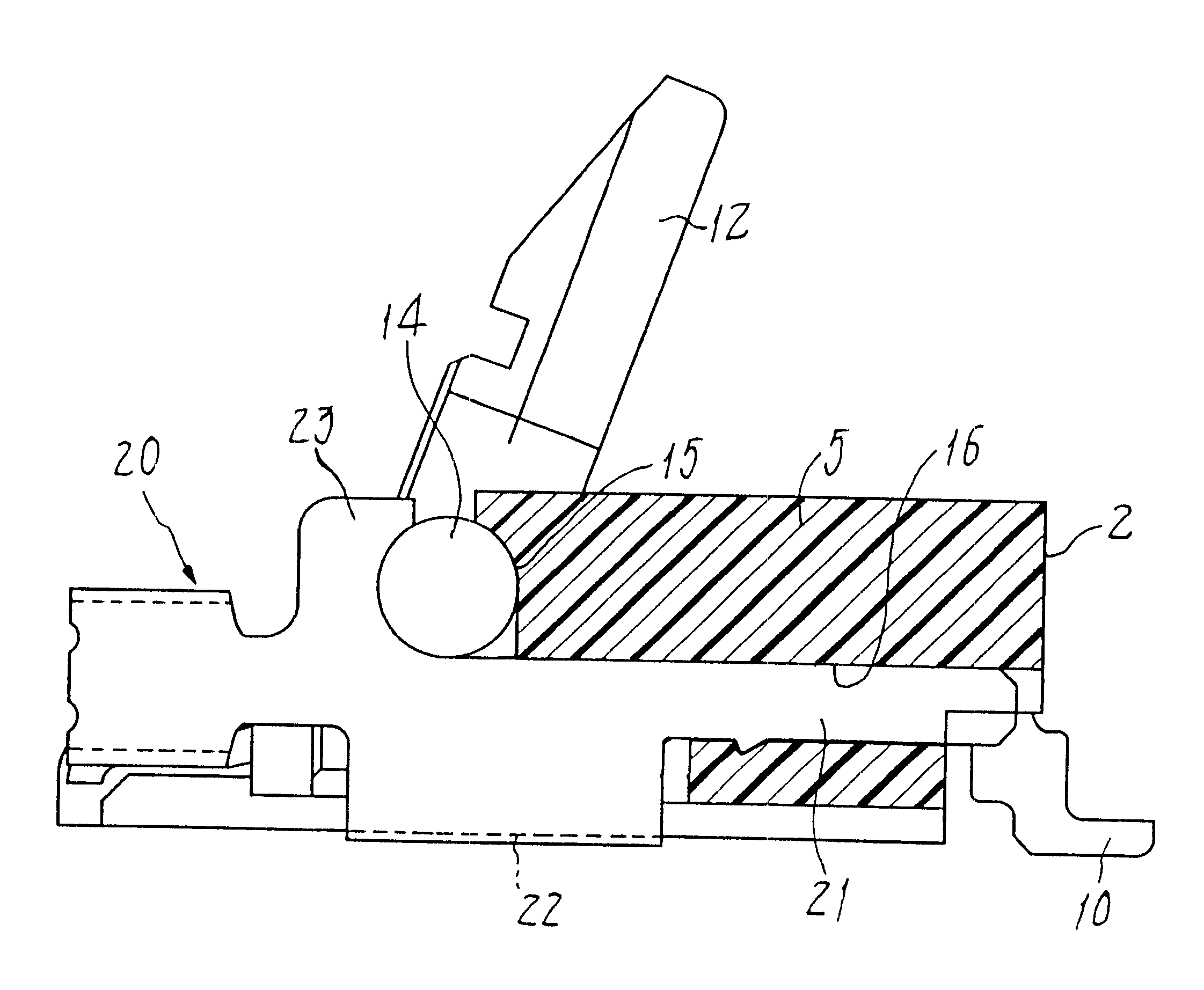
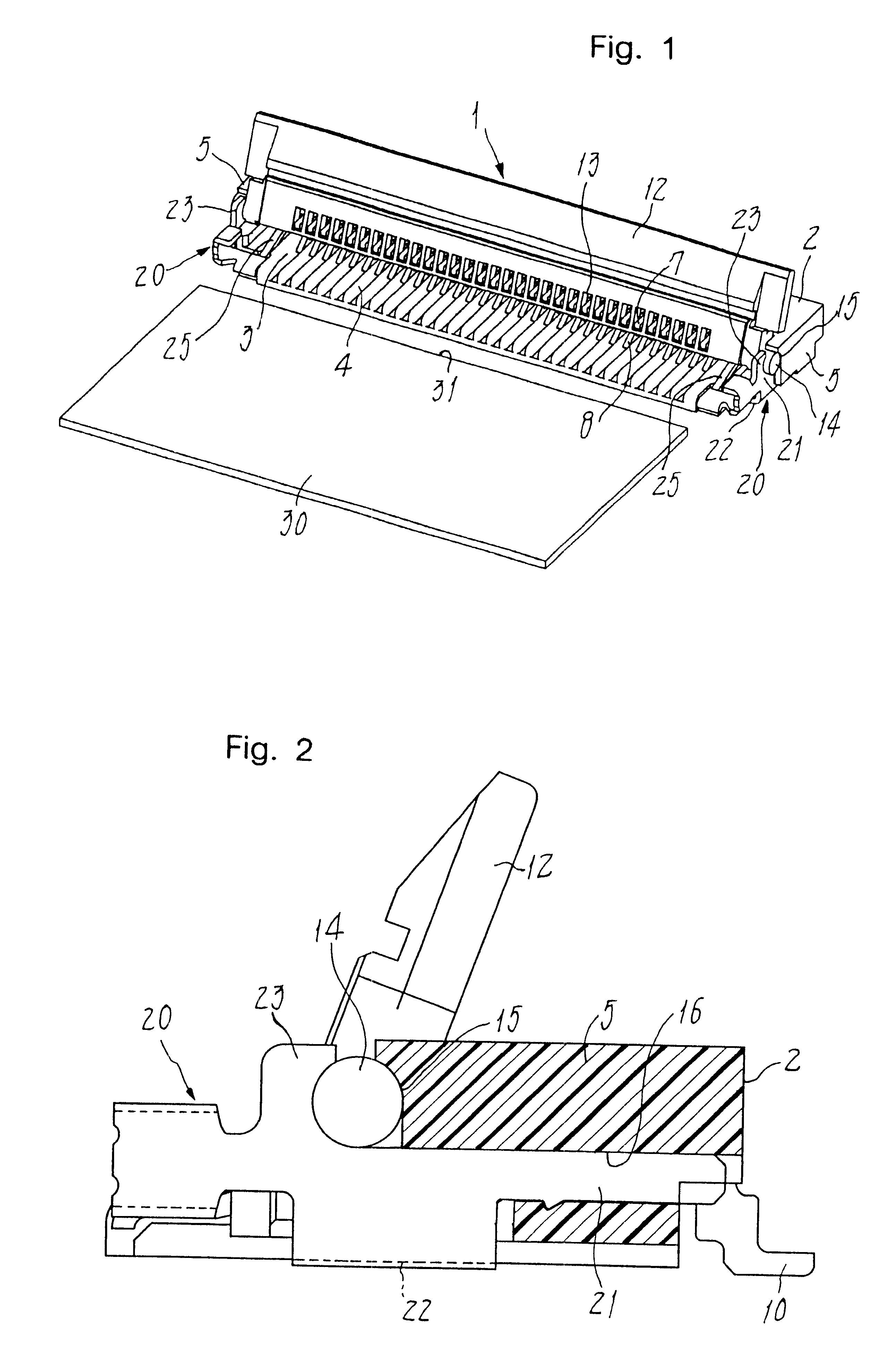
FIGS. 1 to 4 show a connector for use with a flexible circuit board, the connector having compartments formed therein for holding contacts and reinforcement metals.

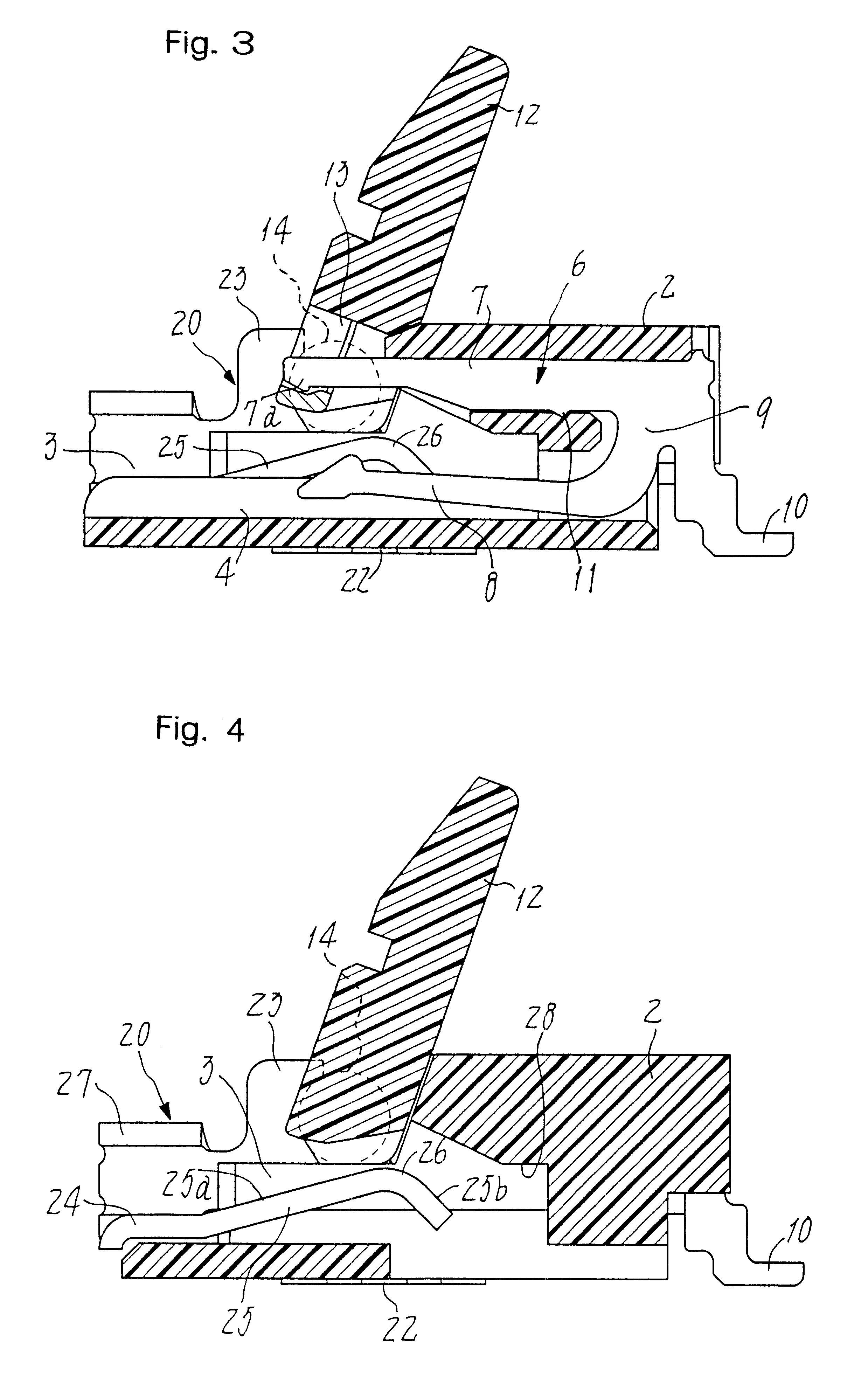
The connector 1 for the flexible circuit board comprises a housing 2 that is formed of an insulating plastics so as to have a recess 3 opened up in the frontal half of the housing 2. Contact receiving grooves 4 are formed and exposed in the recess 3 in order to receive a plurality of the contacts 6 (see FIG. 3) arranged parallel at regular intervals. Pressing means 12 as detailed below are pivoted in the opposite side walls 5 and 5 of the housing, and the reinforcement metals 20 are attached thereto.

As shown in FIG. 3, each contact 6 is a bifurcate piece that was made by punching a thin metal plate. A support arm 7 of the contact 6 extends generally in parallel with a contact beam 8 and is integrally connected thereto by a...


PUM

PropertyMeasurementUnit
flexibleaaaaaaaaaa
conductiveaaaaaaaaaa
sliding displacementaaaaaaaaaa

Abstract

A connector (1) for a flexible circuit board (30) has a housing (2), a pressing means (12), and parallel contacts (6) each having a conductive arm (8) and arranged at a pitch to form a row in the recess (3) of the housing. The pressing means (12) can be swung to close the recess so that an inner end portion of the flexible board (30) overlying the conductive arms (8) will be pressed down onto these arms. Reinforcement metals (20) face one another over the row of the contacts (6) and are attached to opposite sides (5) of the housing (2), so as to be soldered to a rigid printed circuit board. Each reinforcement metal (20) has a resilient support (25) for urging upwards the flexible board (30) in a direction away from the conductive arms (8) so as to keep the board in place.

Description

The present invention relates to a connector for use to connect a flexible circuit board to a relatively rigid printed circuit board.PRIOR ARTSome types of electric connectors known in this field of art are designed each to connect a flexible circuit board to an electronic device, the circuit board being for example a flexible printed cable (FPC) or a flexible flat cable (FFC). Basically, a housing of the known connector has an accessible space in which a plurality of contacts are disposed at regular intervals and in parallel with each other. The known connector comprises also a pressing means that overlies conductive arms of the contacts. This means will be opened and closed to press the flexible circuit board at its end onto these conductive arms. Examples of such a prior art are disclosed for example in Utility Model Laying-Open Gazette No. 6-77186, Japanese Patent No. 3029985 and ibid. No. 3075707 (that corresponds to U.S. Pat. No. 6,056,572).Generally, those prior art connector...

Claims


Application Information

Patent Timeline
Patent Type & Authority Patents(United States)
IPC IPC(8): H01R12/16H01R12/00G01K7/36B60B21/00B60C19/00B60C23/04B60C23/20G01K13/08H01R12/79H01R12/88
CPCH01R12/79H01R12/88H01R12/78
Inventor MIURA, KAZUTO
Owner JST MFG CO LTD
Why Eureka
Try Eureka