Heat exchanger exchange-tube cleaning lance positioning system

a technology of cleaning lance and heat exchanger, which is applied in the direction of cleaning using liquids, machines/engines, lighting and heating apparatus, etc., can solve the problems of reducing plant production, inefficient heat exchange, and dangerous to workers when cleaning the exchange-tubes manually with a high-pressure cleaning lan

Inactive Publication Date: 2004-01-27
BALZER BRENT A
View PDF29 Cites 126 Cited by
  • Summary
  • Abstract
  • Description
  • Claims
  • Application Information

AI Technical Summary

Benefits of technology

FIG. 12 is a front plan view of the three-axis cleaning lance positioning mechanism attached to the heat exchanger head flange of the representative tube sheet of FIGS. 1 and 2 showing the lance gripper and drive assembly

Problems solved by technology

This narrowing causes inefficient heat exchange to occur and can reduce plant production.
Cleaning the exchange-tubes manually with a high pressure cleaning lance is dangerous to the workers because the cleaning lance generates high pressure jets of water that can easily injure a worker and the narrowing buildup remov

Method used


Image

  • Heat exchanger exchange-tube cleaning lance positioning system
  • Heat exchanger exchange-tube cleaning lance positioning system
  • Heat exchanger exchange-tube cleaning lance positioning system

Examples


Embodiment Construction

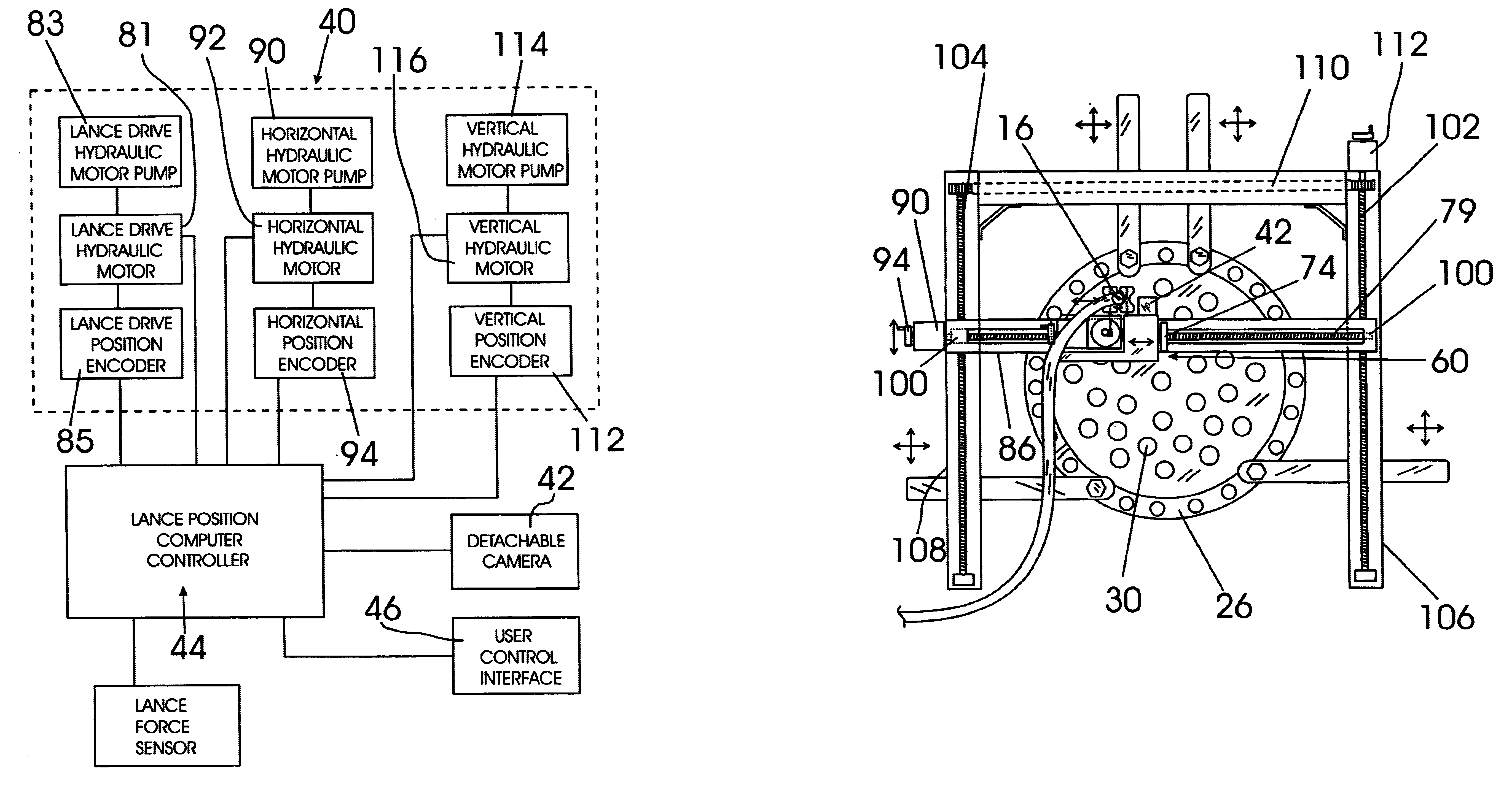
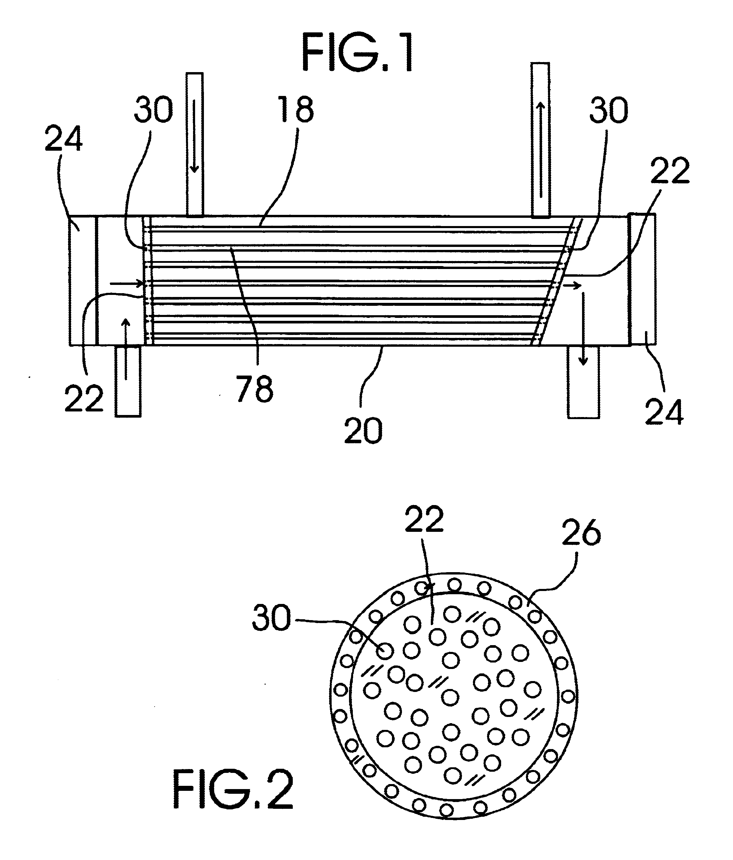
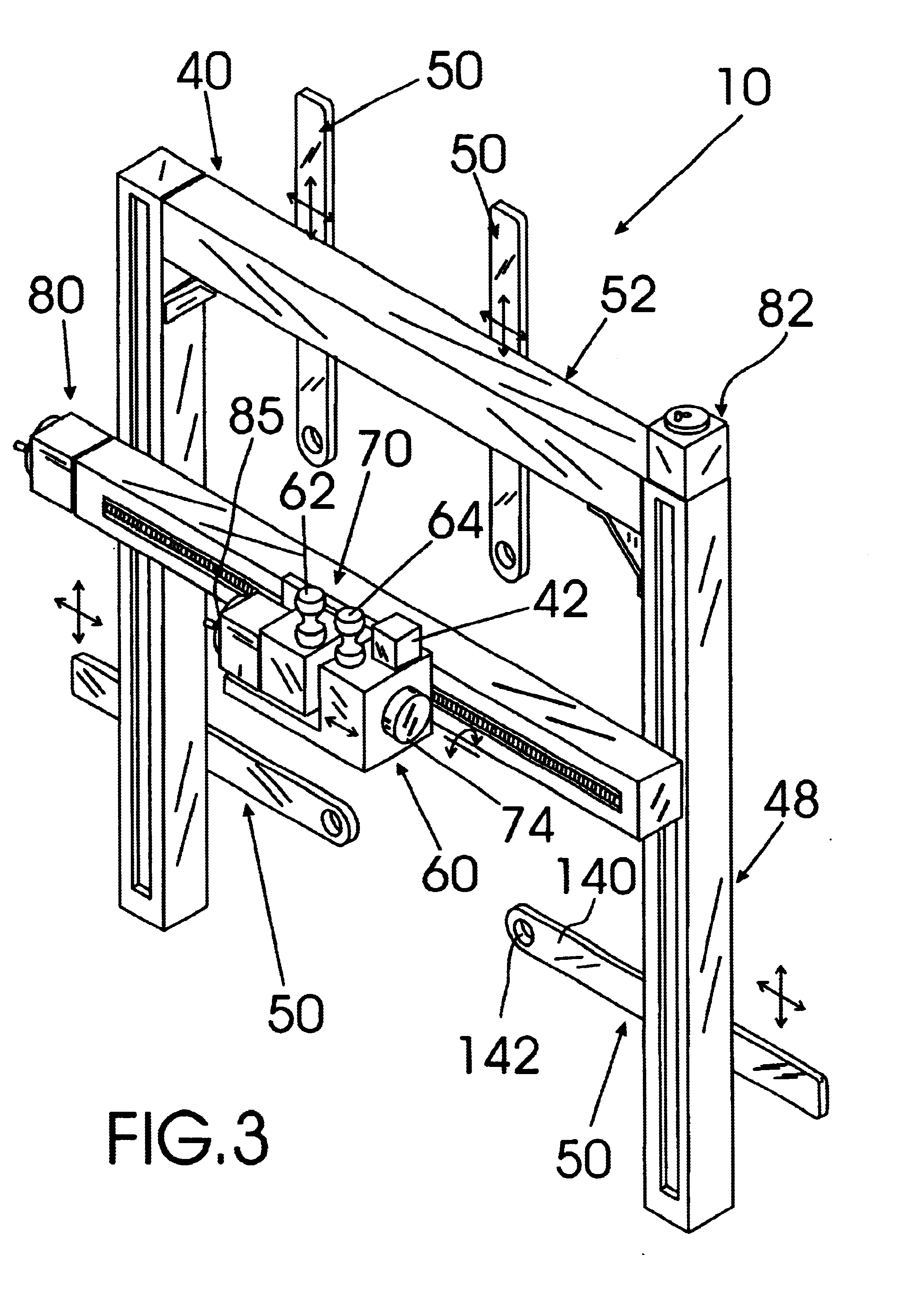
FIGS. 1-12, 3A and 6A show various aspects of an exemplary embodiment of the heat exchanger exchange-tube cleaning lance positioning system of the present invention generally designated 10 (shown in combination in FIGS. 3 and 3A). Heat exchanger exchange-tube cleaning lance positioning system 10 is adapted for manipulating and positioning an exchange-tube cleaning lance, such as rigid, elongated high pressure water exchange-tube cleaning lance 16, for cleaning the exchange-tubes 18 of a heat exchanger 20 having one or more tube sheets 22 accessible by removing an exchanger head 24 connected to a heat exchanger head flange 26; wherein tube sheet 22 has an open end 30 of each of the exchange-tubes 18 in the heat exchanger 20 provided therethrough such that a tip end 34 of exchange-tube cleaning lance 16 may be inserted into and through each of the exchange-tubes 18 of heat exchanger 20 by positioning the tip end 34 of the exchange-tube cleaning lance 16 through an open end 30 of each ...


PUM


Abstract

A heat exchanger exchange-tube cleaning lance positioning system that includes a three axis cleaning lance positioning mechanism that is attachable to the end of a heat exchanger and that is controlled by a lance position computer controller that determines the locations of each of the openings of the exchange-tubes of the heat exchanger by analyzing an image signal generated by a camera mounted to the three axis cleaning lance positioning mechanism and then positions a connected exchange tube cleaning lance into and through each of the exchange-tube passageways to clean the exchange-tube passageways automatically.

Description

The present invention relates to cleaning devices for heat exchangers and more particularly to a heat exchanger exchange-tube cleaning lance positioning system that includes a three axis cleaning lance positioning mechanism that is attachable to the end of a heat exchanger and that is controlled by a lance position computer controller that determines the location of each of the openings of the exchange-tubes of the heat exchanger by analyzing an image signal generated by a camera mounted to the three axis cleaning lance positioning mechanism and then positions a connected exchange tube cleaning lance into and through each of the exchange-tube passageways to clean the exchange-tube passageways automatically.Heat exchangers are used extensively in manufacturing plants to maintain process control over various manufacturing processes such as in the production of plastics and other chemicals. Although these heat exchangers allow the plant to operate, they contain exchange-tubes through w...

Claims


Application Information

Patent Timeline
IPC IPC(8): F28G1/16F28G15/00F28G15/04F28G1/00
CPCF28G1/163F28G15/04F28G15/08
Inventor BALZER, BRENT A.
Owner BALZER BRENT A
Why Eureka
Try Eureka