
Device for dislodging a submersible pool cleaner

Inactive Publication Date: 2004-02-17
PAVEL SEBOR FAMILY TRUST +1
View PDF53 Cites 18 Cited by
  • Summary
  • Abstract
  • Description
  • Claims
  • Application Information

AI Technical Summary

Benefits of technology

In view of the foregoing background, it is an object of the invention to provide a device that is easily adapted to operate with a swimming pool cleaner for dislodging the pool cleaner from an obstacle within the pool. It is further an object to allow a swimming pool cleaner to effectively negotiate out of corners and discontinuities within a pool surface to be cleaned and satisfy a need well known in the pool cleaning art. The present invention provides an effective improvement to the pool cleaner by providing a reliable level of steering.

Problems solved by technology

Typically, when the contour of a pool surface is such that a portion of the cleaner body is able to contact pool side walls while another portion of the cleaner is in contact with the pool bottom surface, the cleaner has a chance of becoming stuck against the pool surfaces.
In such circumstances, the drag induced on the cleaner body will over-ride or may substantially impair the cleaner operation and its normal traversing along the pool surfaces, causing the pool cleaner to remain in one position or stay at that position for an inordinate amount of time.

Method used


Image

  • Device for dislodging a submersible pool cleaner
  • Device for dislodging a submersible pool cleaner
  • Device for dislodging a submersible pool cleaner

Examples


Embodiment Construction

The present invention will now be described more fully hereinafter with reference to the accompanying drawings, in which preferred embodiments of the invention are shown. This invention may, however, be embodied in many different forms and should not be construed as limited to the embodiment set forth herein. Rather, this embodiment is provided so that this disclosure will be thorough and complete, and will fully convey the scope of the invention to those skilled in the art. Like numbers refer to like elements throughout.

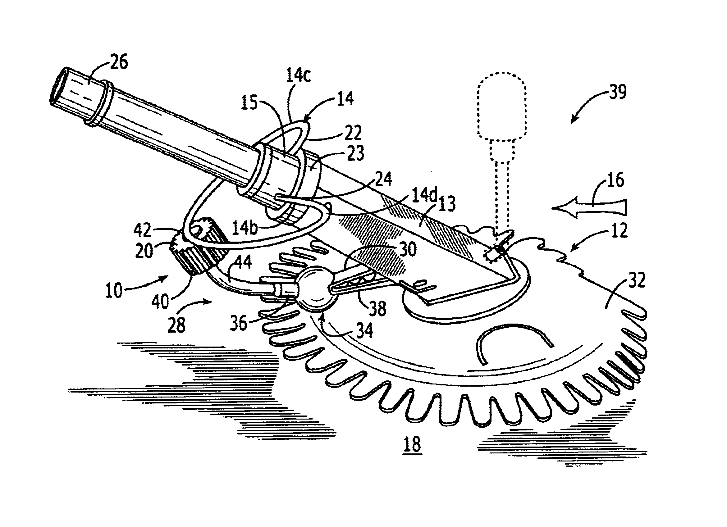
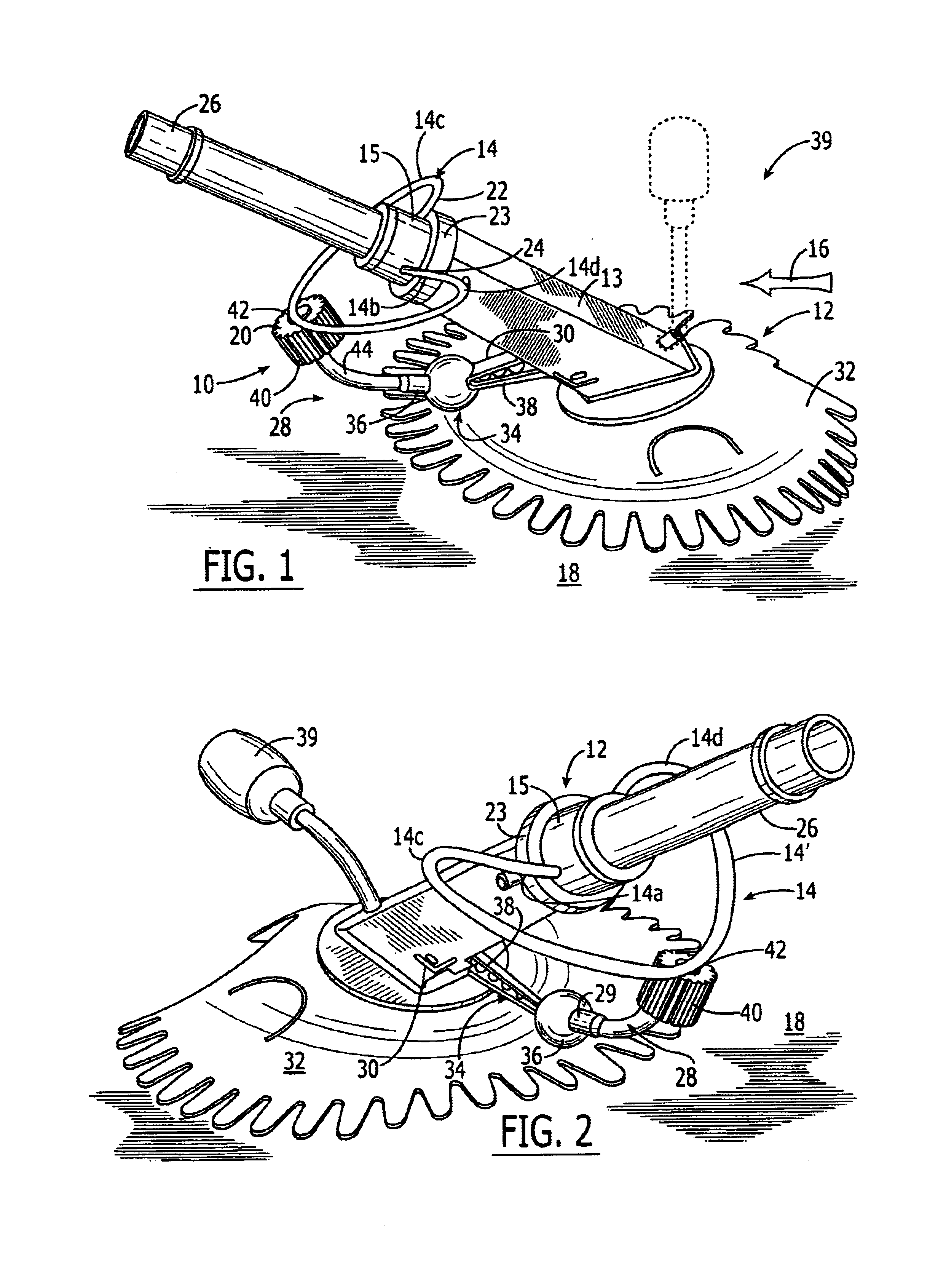
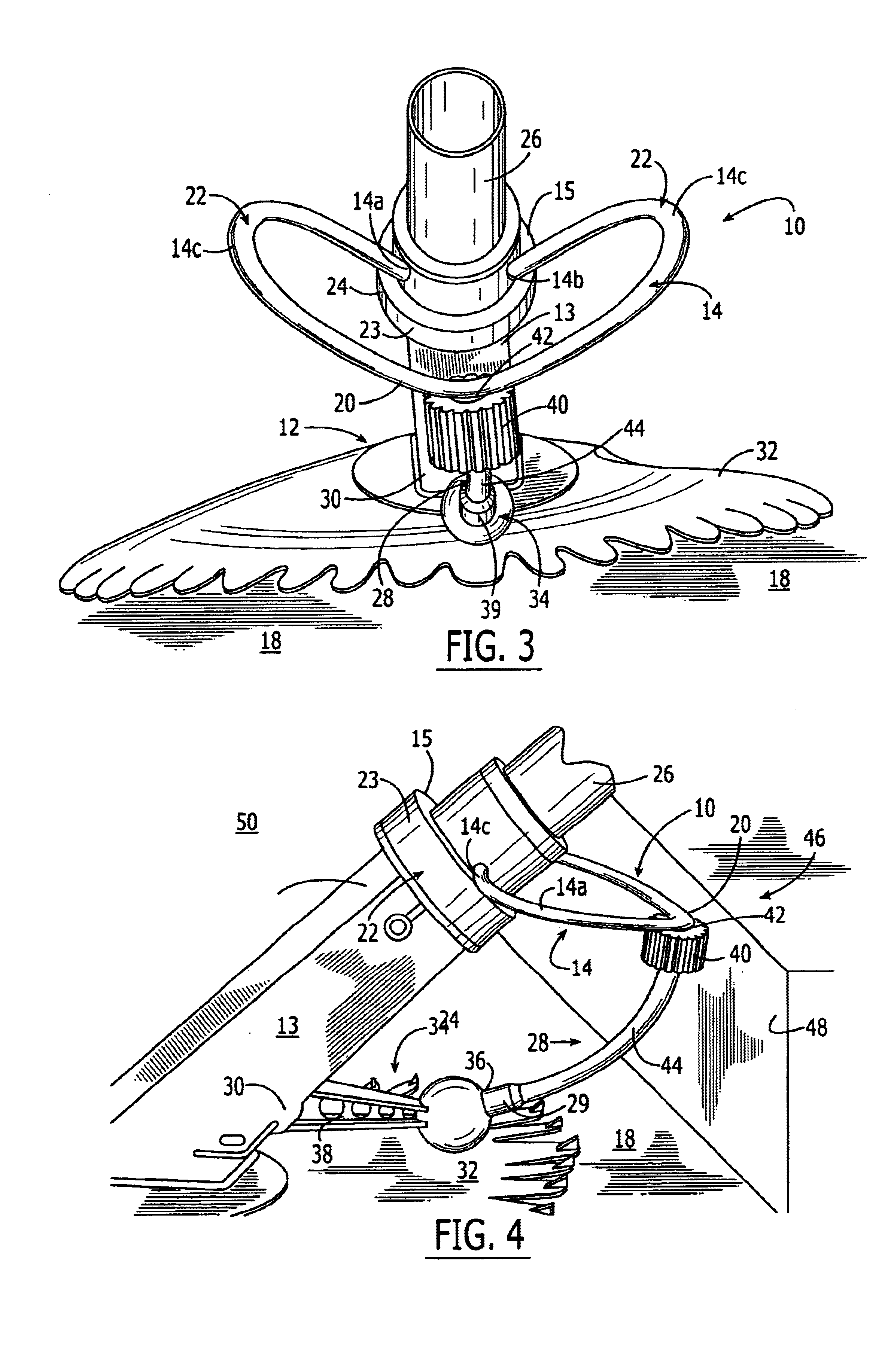
As illustrated initially with reference to FIGS. 1 and 2, the present invention, a device 10 for dislodging a submersible swimming pool cleaner 12 comprises an upper generally semi-circular upper bumper member 14 that extends outwardly from an upper body portion 15 of the pool cleaner 12 generally in a direction of travel 16 and is oriented generally parallel along a surface to be cleaned 18. In one preferred embodiment of the present invention, a forward-most porti...


PUM


Abstract

A device is operably attached to a swimming pool cleaner for dislodging and permitting a steering of the swimming pool cleaner away from obstacles within a swimming pool. The device includes a coupling slidably attached to the swimming pool cleaner near its hose coupling. An upper, generally horizontally positioned, resilient elongate bumper has its opposing ends affixed to the coupling to form the upper bumper into an arcuate shape extending partially around a forward portion of the swimming pool cleaner. A second resilient, elongate vertical bumper has one end attached to the upper bumper and an opposing end attached a weight assembly of the pool cleaner at a location proximate the sealing flange. A roller is attached to the vertical bumper near the upper bumper for rotation thereabout when the swimming pool cleaner encounters an obstacle such as a step from which it is to be dislodged.

Description

The invention relates generally to swimming pool cleaners, and more particularly to the steering and dislodging of pool cleaners operable with a suction hose attached thereto.DESCRIPTION OF BACKGROUND ARTTypically, when the contour of a pool surface is such that a portion of the cleaner body is able to contact pool side walls while another portion of the cleaner is in contact with the pool bottom surface, the cleaner has a chance of becoming stuck against the pool surfaces. This is often the case for pool side walls which are generally perpendicular to the pool bottom surface, such as steps within a pool and square bottomed pools, as described by way of example in U.S. Pat. Nos. 3,803,658 to Raubenheimer, and 4,133,068 to Hofman. In such circumstances, the drag induced on the cleaner body will over-ride or may substantially impair the cleaner operation and its normal traversing along the pool surfaces, causing the pool cleaner to remain in one position or stay at that position for a...

Claims


Application Information

Patent Timeline
IPC IPC(8): E04H4/16E04H4/00
CPCE04H4/1663
Inventor PHILLIPSON, BRIAN H.SEBOR, PAUL
Owner PAVEL SEBOR FAMILY TRUST
Learn More