CV joint protector for ATV

a joint protector and atv technology, applied in the direction of couplings, mechanical control devices, instruments, etc., can solve the problems of bending tubing, locking steering, and exposing the vehicle to high stress, so as to enhance the shield's ability to reduce debris build up, and be easy to clean

Inactive Publication Date: 2004-02-17
SAVANT KEVIN
View PDF0 Cites 43 Cited by
  • Summary
  • Abstract
  • Description
  • Claims
  • Application Information

AI Technical Summary

Benefits of technology

The invention described herein is a protective shield for attachment to the A-arm of an ATV for preventing the intrusion of debris that may damage the suspension or CV joint, the shield having improvements that enhance the shield's abil

Problems solved by technology

All terrain vehicles (ATV) are largely abused by riders traveling over very rough terrain at high speed, thereby subjecting the vehicle to high stress.
However, such tubular construction provides large openings for intrusion by debris, such as sticks and rocks.
Such debris often bends the tubing or becomes wedged in the frame, sometimes even locking up steering and damaging drive shafts and suspension arms.
Most ATV manufacturers do not provide guards or shields to prevent the intrusion of debris into the A-arm.
However, such shields have been found to create additional problems that tend to explain why the ATV manufacturers do not install the

Method used


Image

  • CV joint protector for ATV
  • CV joint protector for ATV
  • CV joint protector for ATV

Examples


Embodiment Construction

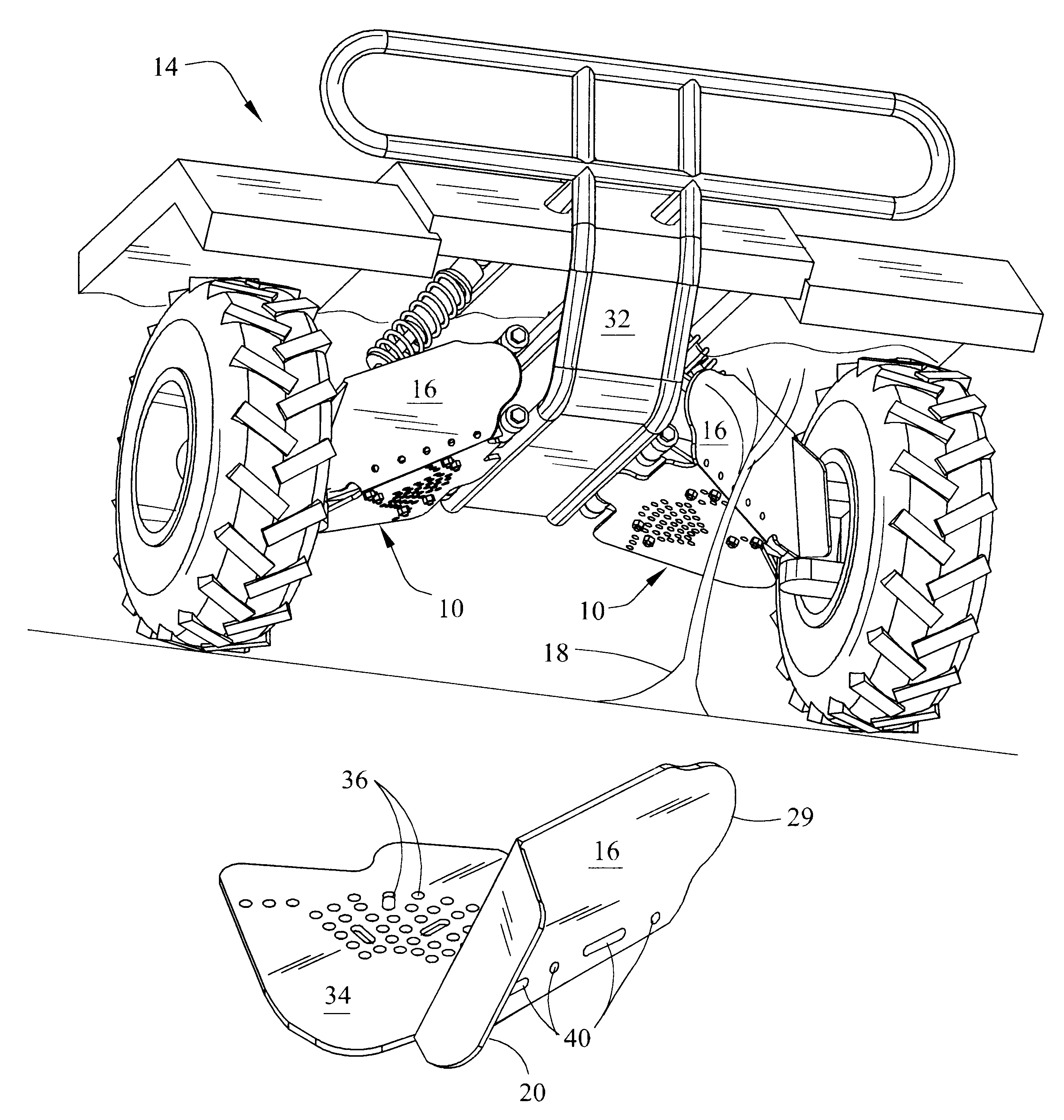
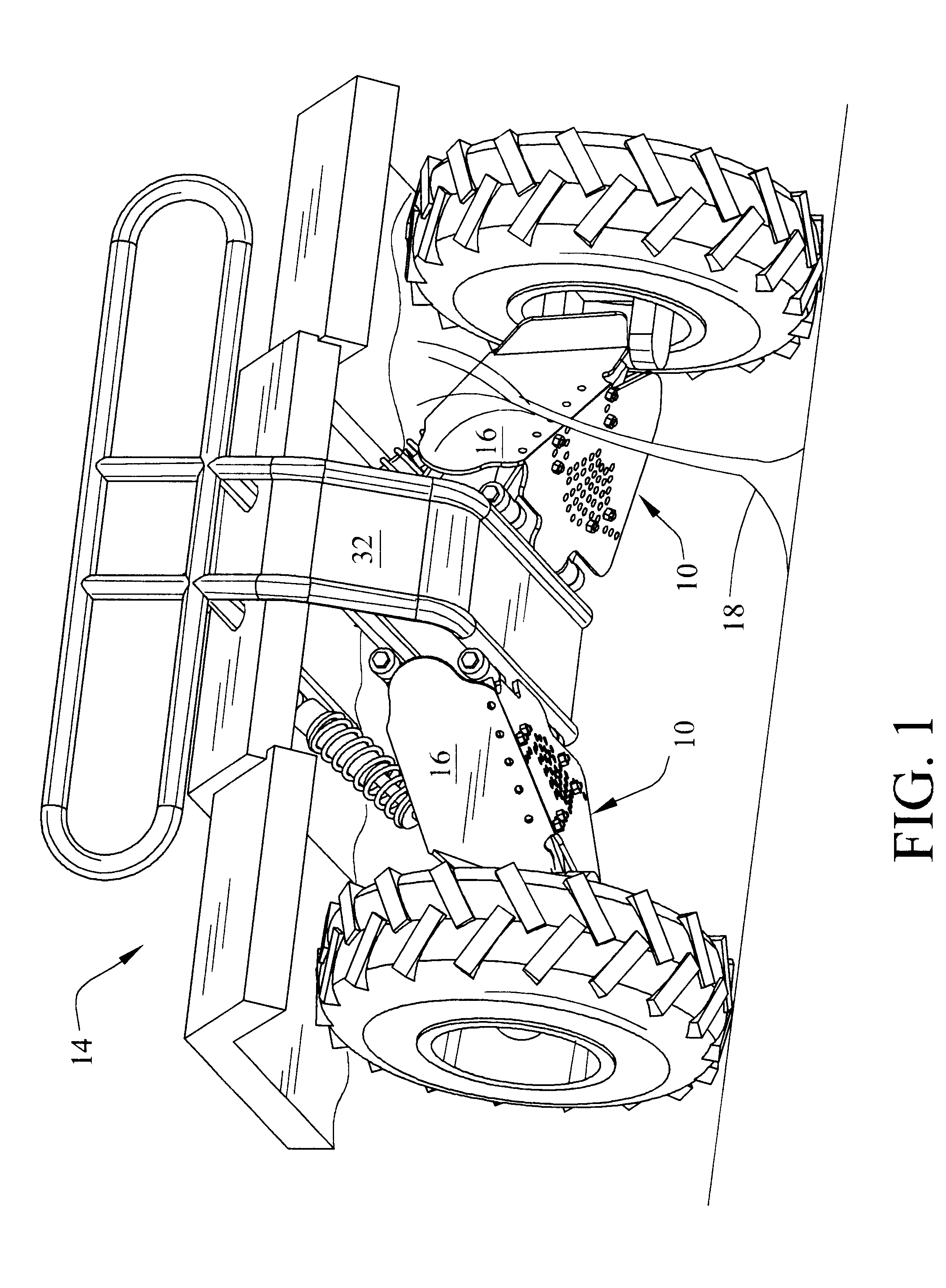
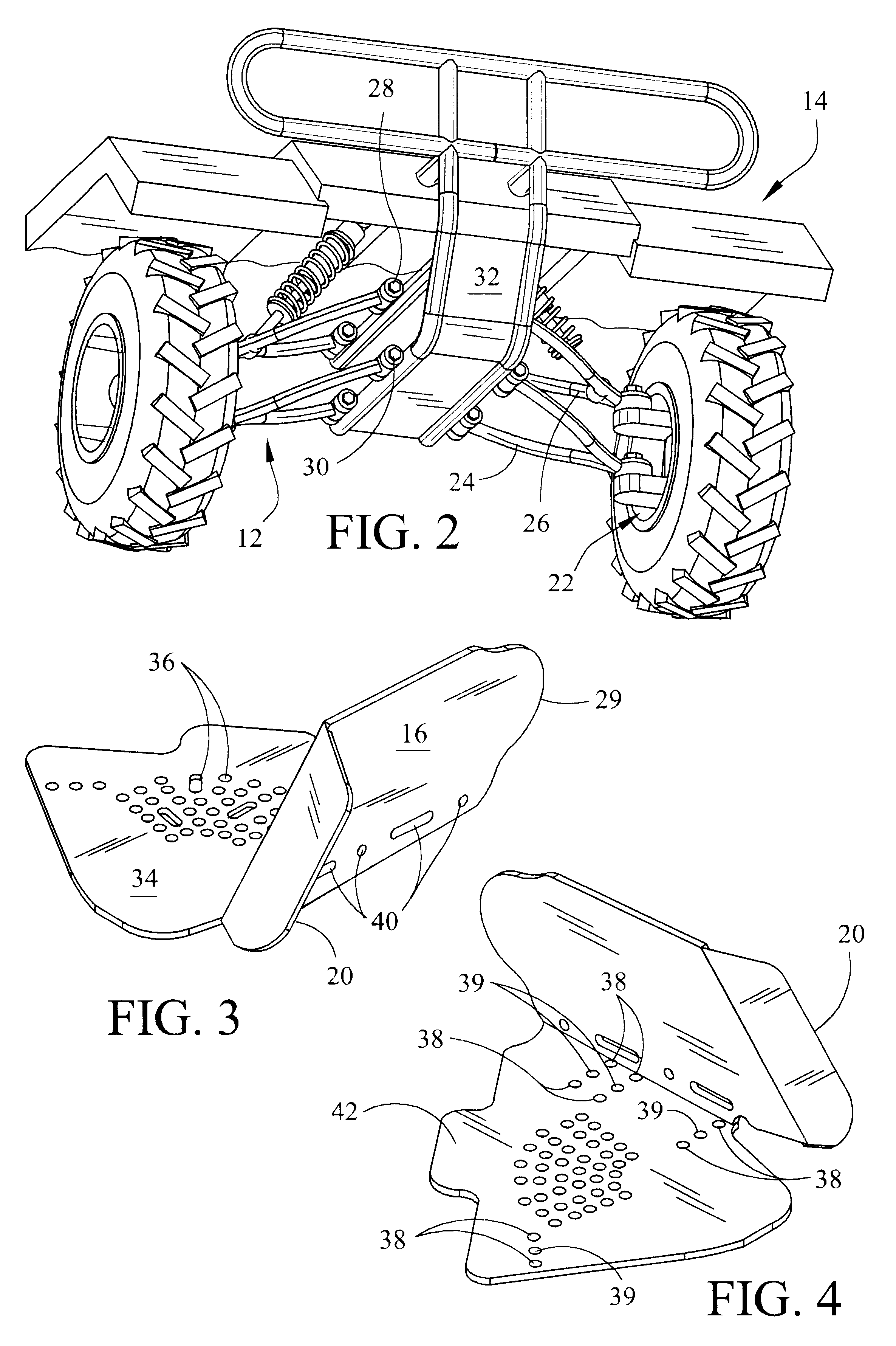
As illustrated in FIG. 1 the improved A-arm protective shields 10 are configured to attach to the front or rear independent suspension A-arms 12 seen in FIG. 2 of most All terrain vehicles (ATV) 14. The front or leading face 16 of the shield, as seen in FIG. 3, is located in front of the A-arm assembly 12 to provide deflection of brush 18 and the like as seen in FIG. 1. The deflector face 20, seen in FIG. 3, is bent at an angle consistent with the convergence of the A-arms 12 and their connection with the wheel assembly 22, seen in FIG. 2, and extends a sufficient distance to deflect debris from entering the space between the upper and lower A-arm suspension members 24,26 as shown in FIG. 2 and as seen in place in FIG. 1. Likewise, the opposite end 29 of the face plate 16 is rounded or radiused to project between the A-arm suspension member connection points 28,30, seen in FIG. 2 and shown in place in FIG. 1, to prevent intrusion of debris adjacent the main frame assembly 32. The mo...


PUM


Abstract

An improved protective shield for attachment to the A-arms of an ATV for preventing the intrusion of debris that may damage the suspension or CV joint. The improvements enhance the shield's ability to reduce debris build up and to be more easily cleaned by suspending the shield below the suspension members and providing washout and drainage holes.

Description

1. FIELD OF THE INVENTIONThis invention relates generally to guards and shields for add-on attachment to All Terrain Vehicles (ATV) and more particularly to a shield for protecting the constant velocity joint of a drive shaft extending through the independent A-arm suspension of such vehicles.2. GENERAL BACKGROUNDAll terrain vehicles (ATV) are largely abused by riders traveling over very rough terrain at high speed, thereby subjecting the vehicle to high stress. Most such vehicles are constructed of tubular frames for lighter weight. However, such tubular construction provides large openings for intrusion by debris, such as sticks and rocks. Such debris often bends the tubing or becomes wedged in the frame, sometimes even locking up steering and damaging drive shafts and suspension arms. Most vulnerable are the constant velocity (CV) or universal joints connecting the drive shafts to the wheels passing through the independent suspension A-arms. These CV joints are generally exposed ...

Claims


Application Information

Patent Timeline
IPC IPC(8): F16D3/00F16D3/84
CPCF16D3/841Y10T74/219Y10T74/2191Y10T74/2193
Inventor SAVANT, KEVIN
Owner SAVANT KEVIN
Why Eureka
Try Eureka