Catalytic growth of single-wall carbon nanotubes from metal particles

a carbon nanotube and metal particle technology, applied in the direction of metal/metal-oxide/metal-hydroxide catalysts, aligned nanotubes, physical/chemical process catalysts, etc., can solve the problems of difficult separation of individual carbon nanotubes from the other reaction products, low nanotube yield, and high cos

Inactive Publication Date: 2004-02-17
RICE UNIV
View PDF5 Cites 251 Cited by
  • Summary
  • Abstract
  • Description
  • Claims
  • Application Information

AI Technical Summary

Problems solved by technology

While this arc discharge process can produce single-wall nanotubes, the yield of nanotubes is low and the tubes exhibit significant variations in structure and size between individual tubes in the mixture.
Individual carbon nanotubes are difficult to separate from the other reaction products and purify.
Although the laser vaporization process produces improved single-wall nanotube preparations, the product is still heterogeneous, and the nanotubes are too tangled for many potential uses of these materials.
In addition, the vaporization of carbon is a high-energy process and is inherently costly.
However, such components have not been produced up to now.
Using the known methods of catalyst particle preparation, it is not possible to provide nanoparticles with a uniform optimum size to produce only single-wall nanotubes, and the growth process of Dai, et al., does not provide high yields of single-wall nanotubes because the larger particles produce multiwall nanotubes.
Catalyst particles of greater than about 2 nanometers in diameter are more likely to form multiwall nanotubes, and since they are rendered ineffective by the process, the only remaining active catalyst particles support growth of primarily single-wall nanotubes.

Method used


Image

  • Catalytic growth of single-wall carbon nanotubes from metal particles
  • Catalytic growth of single-wall carbon nanotubes from metal particles
  • Catalytic growth of single-wall carbon nanotubes from metal particles

Examples


example

In order to facilitate a more complete understanding of the invention, an Example is provided below. However, the scope of the invention is not limited to specific embodiments disclosed in this Example, which is for purposes of illustration only.

1. Preparation

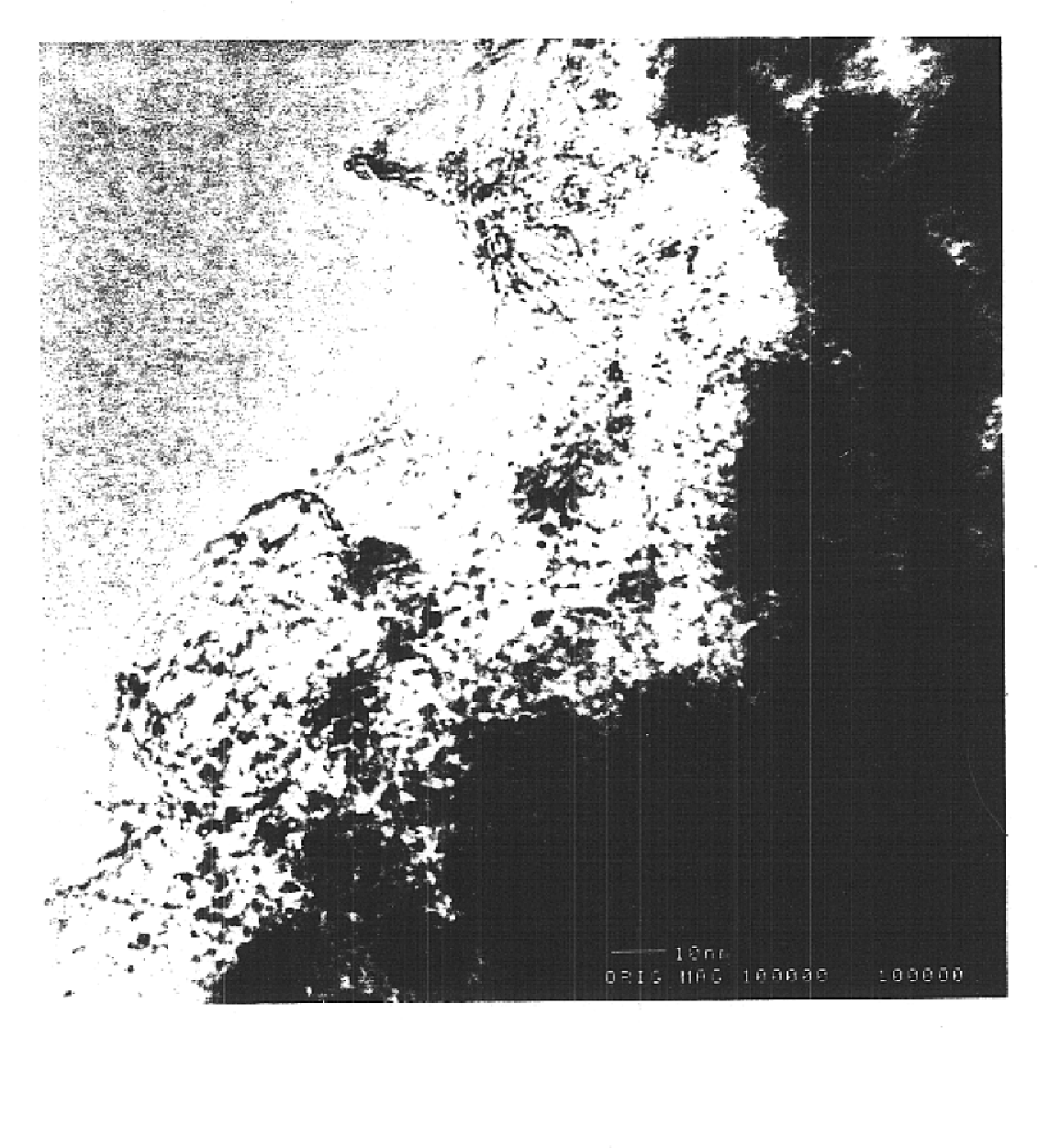
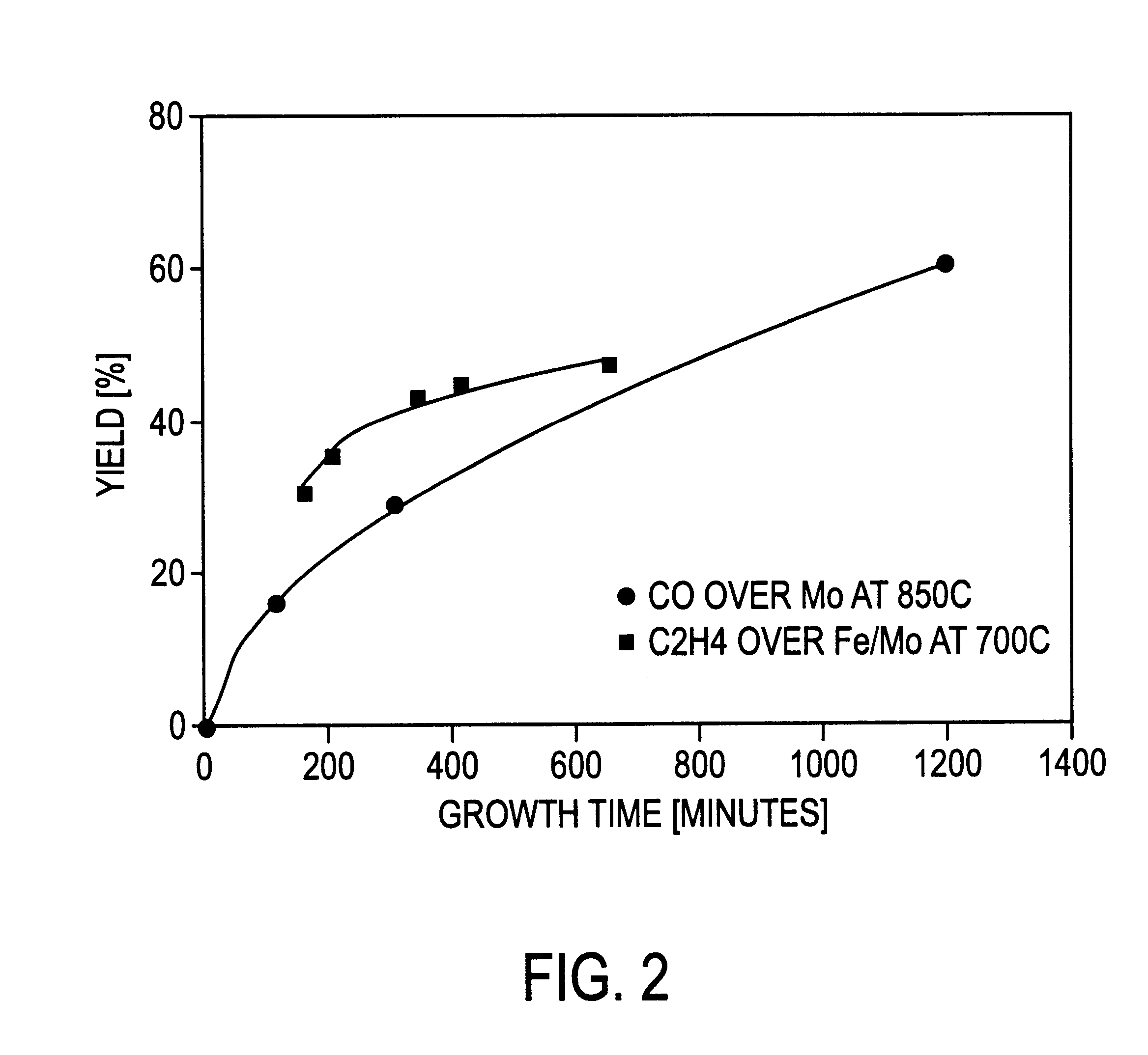
Single wall carbon nanotubes may be grown by passing carbon-containing gases (CO or C.sub.2 H.sub.4) at elevated temperatures over nanometer-size metal particles supported on larger (10-20 nm) alumina particles. Two different metal catalysts may be used, one containing pure Mo, the other containing Fe and Mo. The ratio of FE to Mo may be 9:1. Both catalysts were made using a method known in the art.

For each growth experiment, a quartz boat containing a carefully weighed amount (typically 20 mg) of the catalyst powder was placed in the center of a 1 inch quartz tube furnace. The system was purged with Ar, then heated under flowing reactant gases to an elevated temperature for a controlled time. The resulting catalyst material, w...


PUM

PropertyMeasurementUnit
diameteraaaaaaaaaa
diameteraaaaaaaaaa
partial pressureaaaaaaaaaa

Abstract

Single-walled carbon nanotubes have been synthesized by the catalytic decomposition of both carbon monoxide and ethylene over a supported metal catalyst known to produce larger multi-walled nanotubes. Under certain conditions, there is no termination of nanotube growth, and production appears to be limited only by the diffusion of reactant gas through the product nanotube mat that covers the catalyst The present invention concerns a catalyst-substrate system which promotes the growth of nanotubes that are predominantly single-walled tubes in a specific size range, rather than the large irregular-sized multi-walled carbon fibrils that are known to grow from supported catalysts. With development of the supported catalyst system to provide an effective means for production of single-wall nanotubes, and further development of the catalyst geometry to overcome the diffusion limitation, the present invention will allow bulk catalytic production of predominantly single-wall carbon nanotubes from metal catalysts located on a catalyst supporting surface.

Description

1. Field of the InventionThis invention relates generally to methods of producing single-wall carbon nanotubes, and to catalysts for use in such methods.2. Description of Related ArtFullerenes are closed-cage molecules composed entirely of sp2-hybridized carbons, arranged in hexagons and pentagons. Fullerenes (e.g., C60) were first identified as closed spheroidal cages produced by condensation from vaporized carbon.Fullerene tubes are produced in carbon deposits on the cathode in carbon arc methods of producing spheroidal fullerenes from vaporized carbon. Ebbesen et al. (Ebbesen I), "Large-Scale Synthesis Of Carbon Nanotubes," Nature, Vol. 358, p. 220 (Jul. 16, 1992) and Ebbesen et al., (Ebbesen II), "Carbon Nanotubes," Annual Review of Materials Science, Vol. 24, p. 235 (1994). Such tubes are referred to herein as carbon nanotubes. Many of the carbon nanotubes made by these processes were multi-wall nanotubes, i.e., the carbon nanotubes resembled concentric cylinders. Carbon nanotu...

Claims


Application Information

Patent Timeline
Patent Type & Authority Patents(United States)
IPC IPC(8): D01F9/127D01F9/12
CPCB82Y30/00B82Y40/00C01B31/0233D01F9/127B01J23/28B01J23/881B01J35/0013B01J35/023C01B2202/02C01B2202/08C01B2202/36Y10S977/75Y10S977/843Y10S977/845C01B32/162
Inventor SMALLEY, RICHARD E.HAFNER, JASON H.COLBERT, DANIEL T.SMITH, KEN
Owner RICE UNIV
Why Eureka
Try Eureka