

Method of making carbon nanotube arrays, and thermal interfaces using same
a carbon nanotube and thermal interface technology, applied in the field of carbon nanotube array making and thermal interface making, can solve the problems of high-polished surfaces, increased thermal resistanc, and reduced surface bonding quality
- Summary
- Abstract
- Description
- Claims
- Application Information
AI Technical Summary
Benefits of technology
Problems solved by technology
Method used
Image

Examples
Embodiment Construction
A method and apparatus for using carbon nanotubes are described. In the following description, for the purposes of explanation, numerous specific details are set forth in order to provide a thorough understanding of the present invention. It will be apparent, however, to one skilled in the art that the present invention may be practiced without these specific details. In other instances, well-known structures and devices are shown in block diagram form in order to avoid unnecessarily obscuring the present invention.
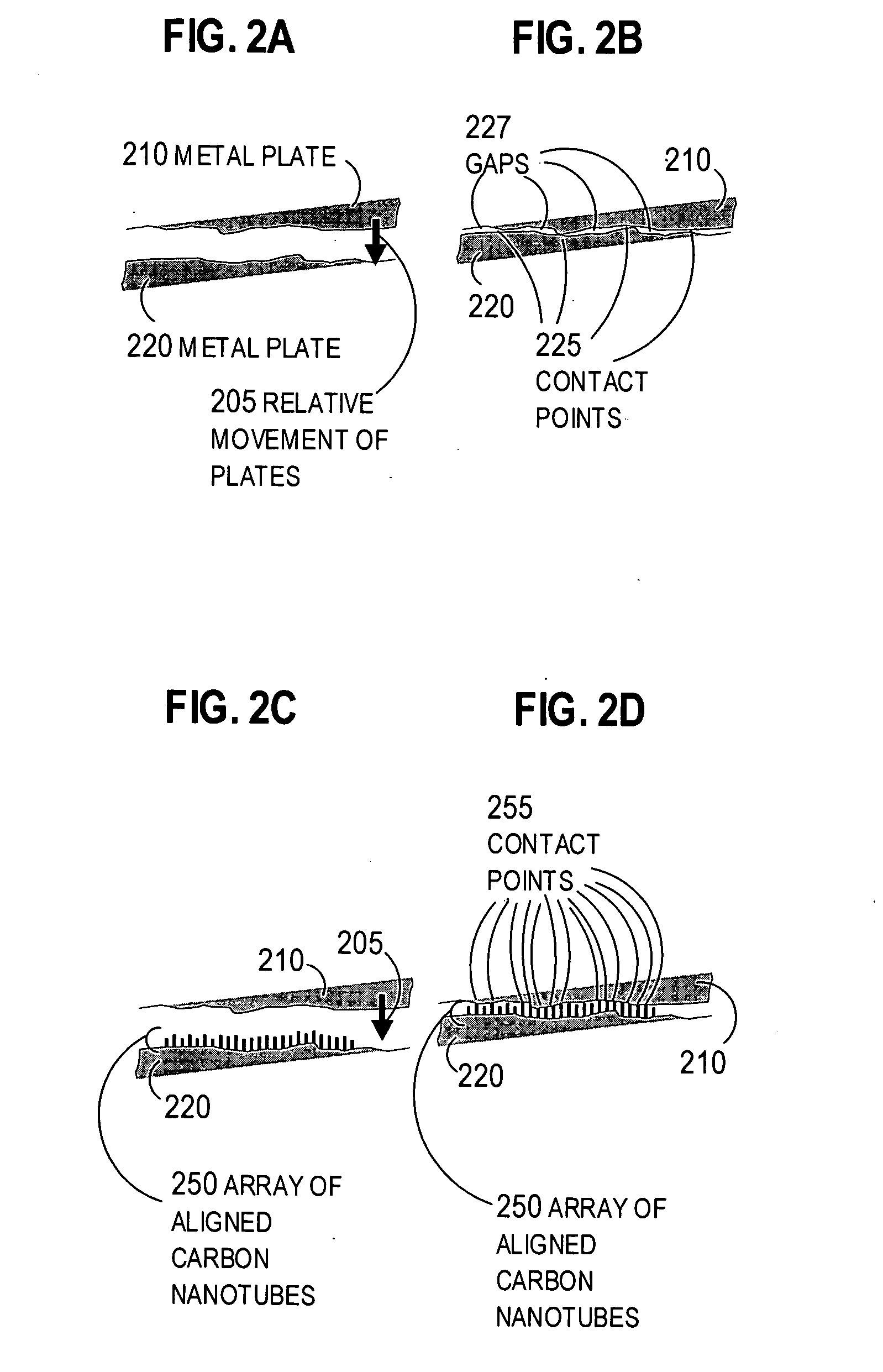
Embodiments of the invention are described in the context of thermal interfaces in thermal switches, but the invention is not limited to this context. In other embodiments, the invention provides an array of carbon nanotubes for any purpose, including, but not limited to, a fixed thermal interface between fixed components in electric circuits or other devices, for structural components such as in micro-electromechanical systems (MEMS), or for electrical conductivity betw...
PUM
| Property | Measurement | Unit |
|---|---|---|
| Fraction | aaaaa | aaaaa |
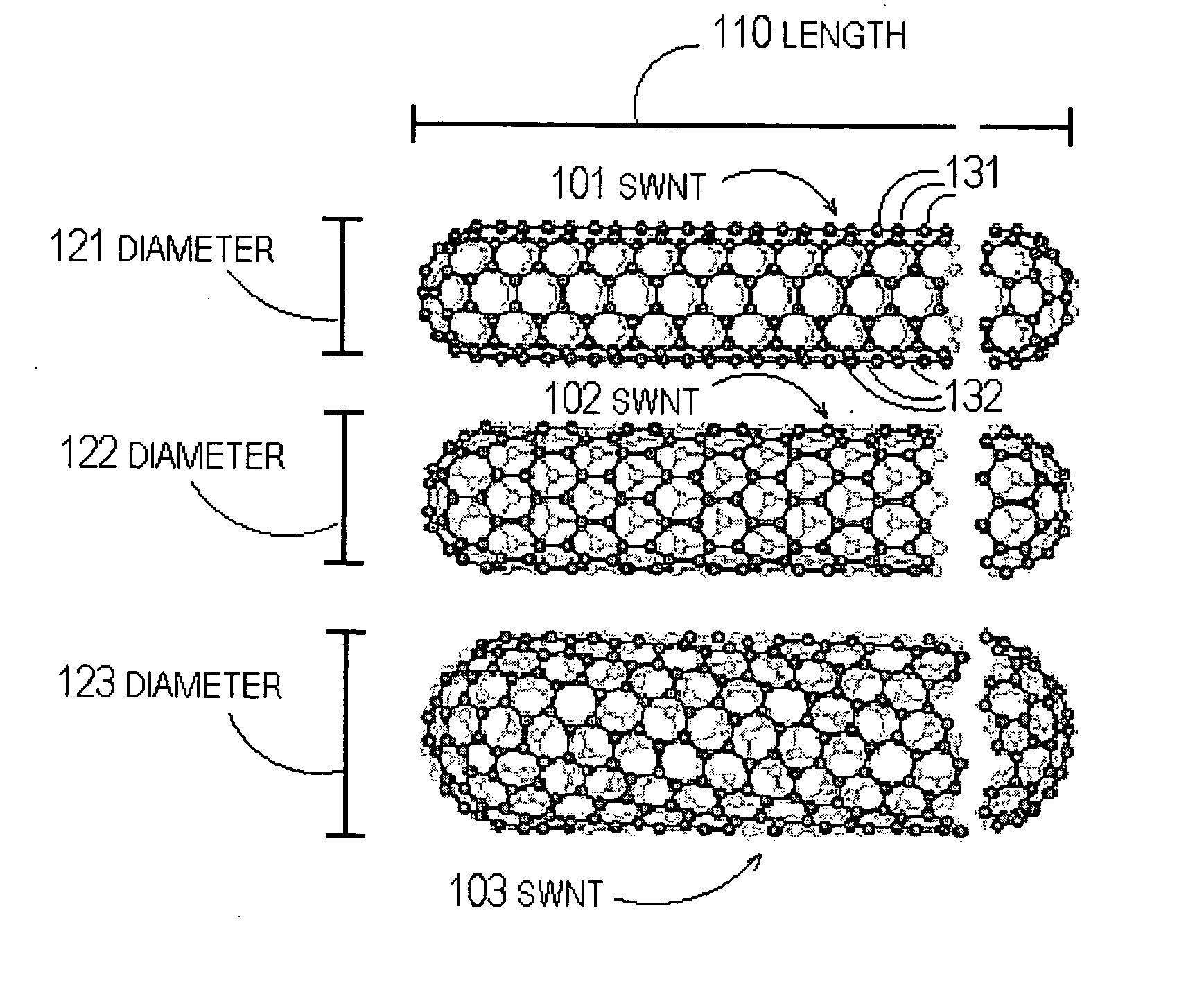
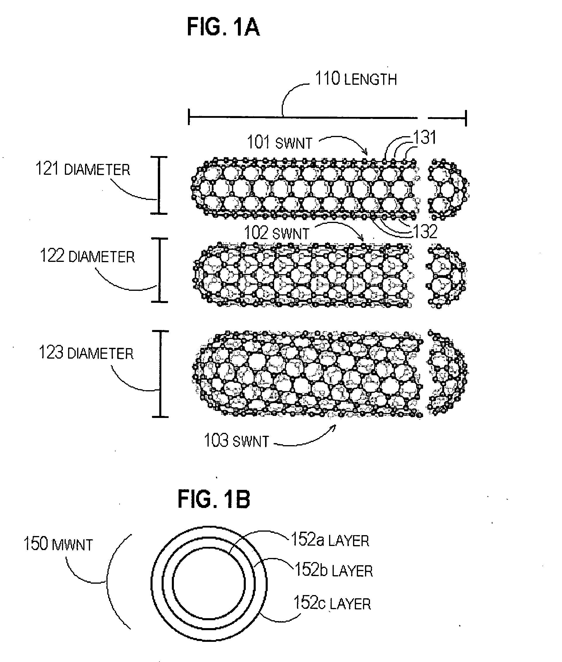
| Diameter | aaaaa | aaaaa |
| Diameter | aaaaa | aaaaa |
Abstract
Description
Claims
Application Information