Laser ablation cleaning

a technology of laser ablation and cleaning, applied in the field of laser ablation cleaning, can solve the problems of large volume of waste, affecting the effect of laser ablation efficiency, and causing residues on the target surfa

Inactive Publication Date: 2004-02-17
RF ENVIROTECH
View PDF16 Cites 66 Cited by
  • Summary
  • Abstract
  • Description
  • Claims
  • Application Information

AI Technical Summary

Problems solved by technology

Nearly all current coating removal technologies exhibit one or more of three shortcomings: (1) they can cause damage to the substrate, (2) they do not clean out surface pores, or (3) they result in a volume of waste that is larger than the volume of removed coating material (e.g., it takes about 100 pounds of sand to remove 1 pound of aged lead-based paint by sand-blasting).
Further, many existing designs inject or suck air in parallel to, and from one side, of the surface being cleaned, and then evacuate it from the other side; such designs tend to leave residue ("sooting") on the target surface due to asymmetric flow.

Method used


Image

  • Laser ablation cleaning
  • Laser ablation cleaning
  • Laser ablation cleaning

Examples


Embodiment Construction

)

The present invention is useful for the removal of coatings such as paint, rust, varnish, lacquer, and the like, or the removal of corrosion or oxidation build-up, from substrate materials such as metals, concrete, wood, certain plastics, composite materials, and glass.

The laser-ablation invention for surface cleaning results in faster, cheaper, more efficient industrial-speed cleaning. The invention also results in the reduction of certain hazardous materials to harmless molecules, reducing the amount and types of hazardous materials deposited in landfills.

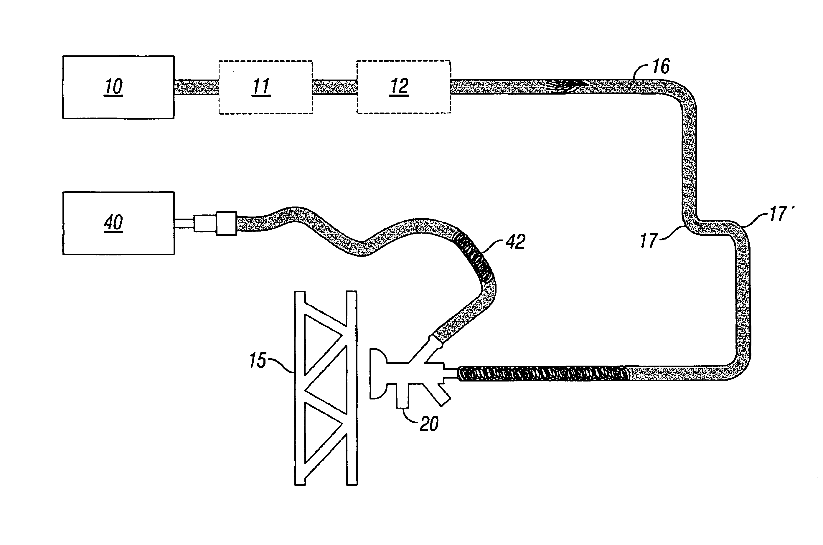
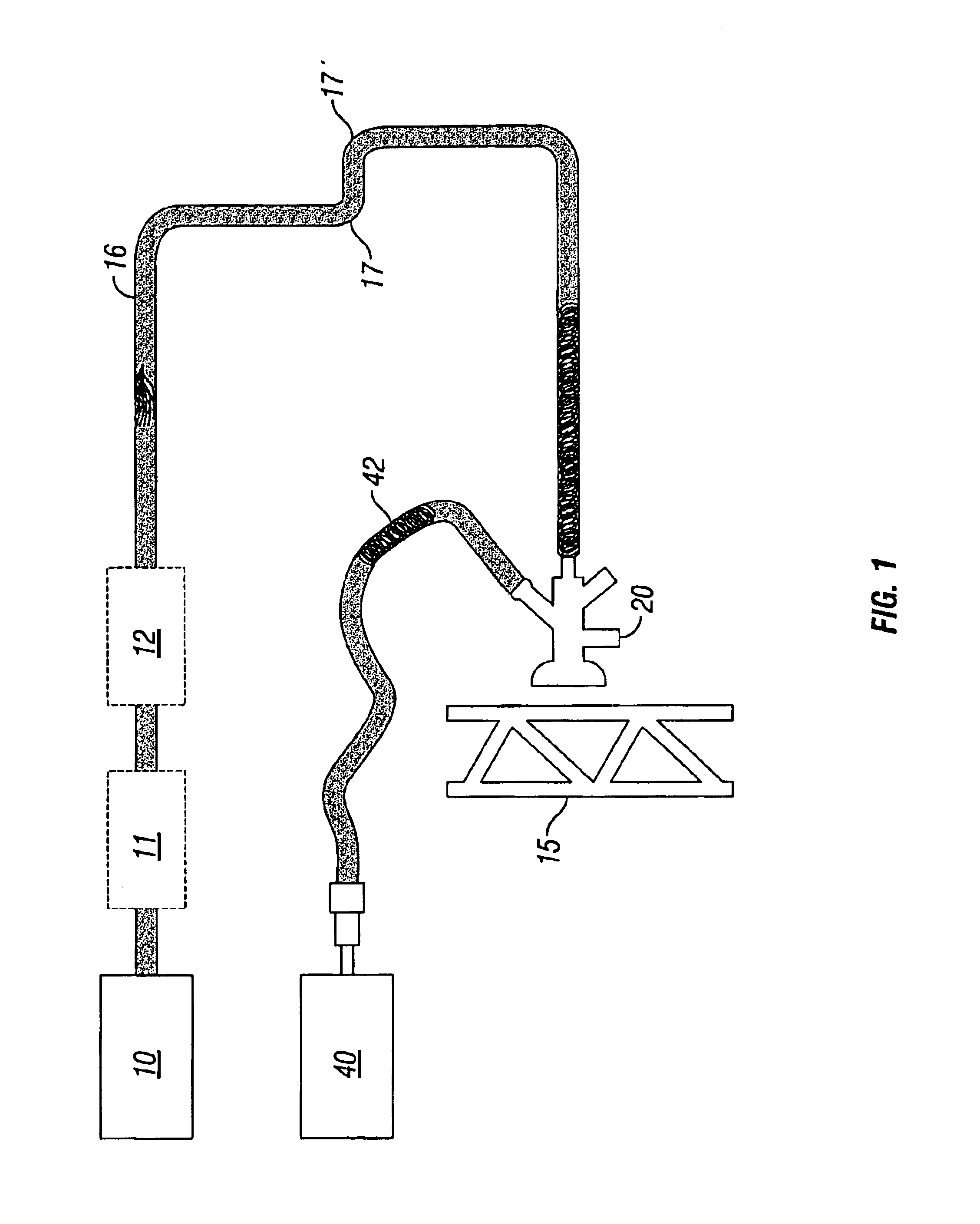
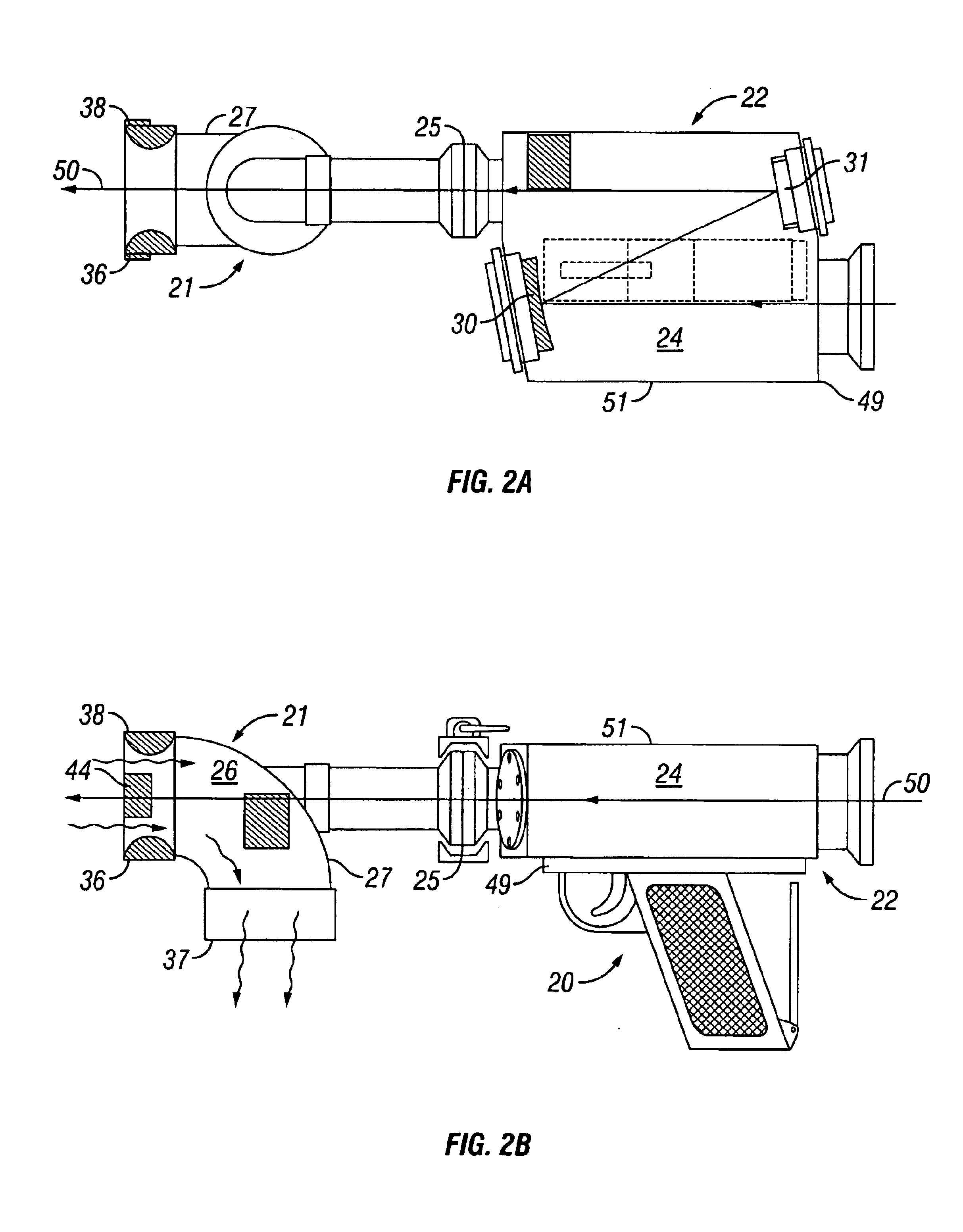
In laser ablation according to one embodiment of the present invention, a laser beam is delivered via optics to an ablation-material capture / suction nozzle, or "cleaning head." The laser beam passes through the nozzle and impinges onto the surface being cleaned. The laser light causes ablation of the coating, resulting in released gases, vapors and particulates. The nozzle is attached to a vacuum hose that sucks up the ablated m...


PUM

PropertyMeasurementUnit
Anglesaaaaaaaaaa
sizeaaaaaaaaaa
strength-to-weight ratioaaaaaaaaaa

Abstract

Laser ablation cleaning apparatus. An optical box containing mirrors for specially directing laser light, such as repeated pulsed CO2 laser, is mounted in a hand-held cleaning head or in a custom work head. The hand-held cleaning head can be used to safely direct laser energy to a surface to be cleaned; the laser beam ablates from the surface coatings, corrosion, and the like without harming the substrate. The custom work head is removably mountable upon the iron core stack of a conventional commercial electric generator, and features an optics box carriage that is selectively movable along the axis of the stack to direct a laser beam into the slots of the stack for cleaning.

Description

1. Field of the Invention (Technical Field)The present invention relates to the use of directed laser energy to ablate materials from surfaces, particularly for the removal of contaminants and buildups from industrial components, especially methods and apparatus for laser ablation cleaning of commercial electrical generators.2. Background ArtLaser ablation is not new. But all traditional ablation theories are based on a thermal-process model, delivering enough energy fast enough to take a scud coating directly to a vapor state. In the present invention, resonant energy is coupled directly into bond vibrational frequencies. For example, hydrocarbon molecules that make up linseed oil are literally torn apart by quickly forcing the vibrations between atoms making up the molecules, such as C--C, C.dbd.C, C--O, and C--H, to vibrate so violently that the bonds break. This is different from thermal-process models for laser ablation.There commonly are many kinds of coatings such as paint, g...

Claims


Application Information

Patent Timeline
Patent Type & Authority Patents(United States)
IPC IPC(8): B08B7/00B23K26/14
CPCB08B7/0042B23K26/0096B23K26/032B23K26/1405B23K26/1441B23K26/1458B23K26/1462B23K26/142B23K26/1436
Inventor FREIWALD, DAVID A.YOUNGMAN, MICHAELYOUNGMAN, KEVIN
Owner RF ENVIROTECH
Why Eureka
Try Eureka