Oil leak diversion and collection system for mechanical shaft seals

a mechanical shaft seal and oil leakage collection technology, which is applied in the direction of machines/engines, positive displacement liquid engines, lighting and heating apparatus, etc., can solve the problems of internal oil leakage through the crankcase, unnecessary component replacement of mechanical shaft seal components, and oil leakage across the seal face. to achieve the effect of reducing oil leakag

Inactive Publication Date: 2004-03-02
CARRIER CORP
View PDF2 Cites 14 Cited by
  • Summary
  • Abstract
  • Description
  • Claims
  • Application Information

AI Technical Summary

Benefits of technology

It is an object of the present invention to...

Problems solved by technology

Oil leakage across the seal faces is a common problem with any mechanical shaft seal.
If such oil is allowed to leak unabated, external oil leakage through the crankcase can result.
Typically such leakage is more visually unpleasing and alarming rather than detrimental to compressor function; howev...

Method used


Image

  • Oil leak diversion and collection system for mechanical shaft seals
  • Oil leak diversion and collection system for mechanical shaft seals
  • Oil leak diversion and collection system for mechanical shaft seals

Examples


Embodiment Construction

The invention as described herein will refer to a reciprocating compressor for use with an air conditioning or refrigeration system. Although this compressor is shown in a configuration and described relative to incorporation with a refrigeration circuit within an air conditioning system or a refrigeration system it is to be understood that this method of oil collection and diversion is equally applicable to other types of compressors, pumps and other applications.

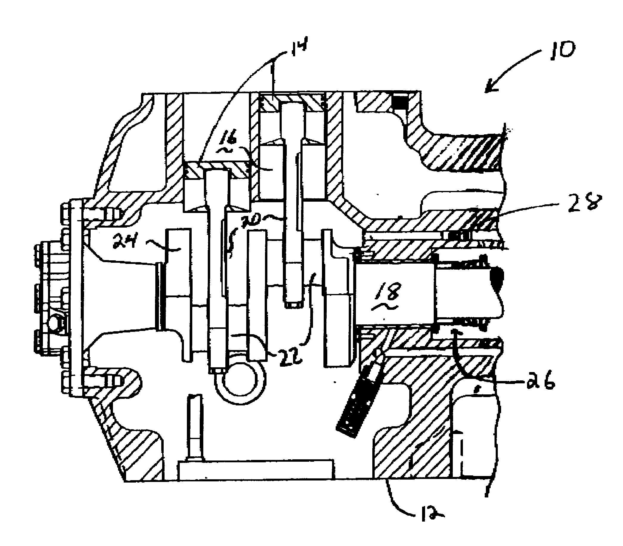
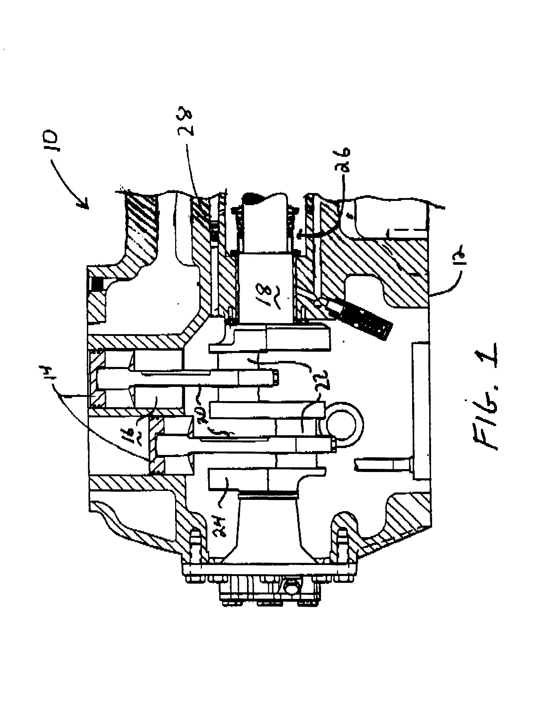
Referring now to FIG. 1, shown is a compressor 10 including shell 12. Working pistons 14 are mounted for reciprocating movement within cylinders 16. Each piston is connected to crankshaft 18 via a connecting rod 20. Connecting rod 20 is secured around offset portion 22 of crankshaft 18. Crankshaft 18 includes counterbalance 24 for balancing the rotational irregularities in the crankshaft. The crankshaft is mounted and rotates within sleeve 28 and extends through shaft seal cavity 26 of housing 12.

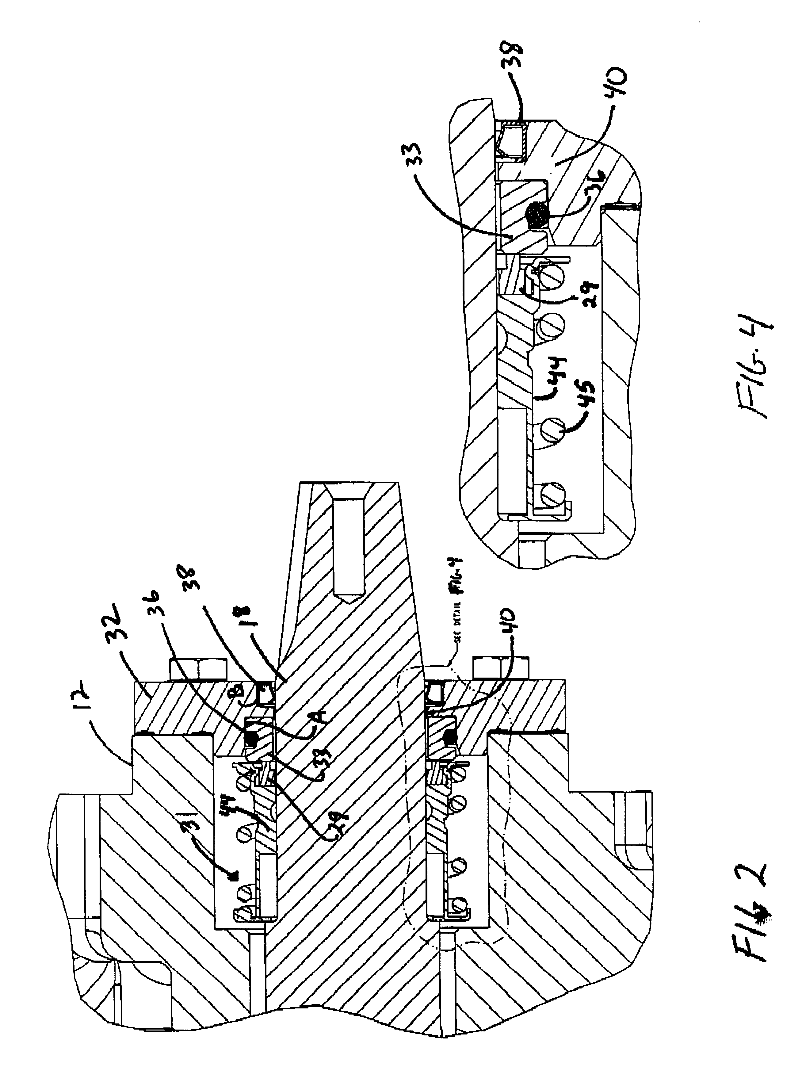
Referring to FIG. 2 and 4,...


PUM


Abstract

A compressor oil diversion and collection system used in a compressor having a housing, a crankshaft having shaft seals, refrigerant and a compression device for compressing the refrigerant. The system includes a shaft sealing mechanism that uses a lubricant for preventing compressor refrigerant from leaking out of the compressor housing and has a space where the lubricant collects. A diversion mechanism is deployed for directing excess amounts of said lubricant from the space to a receiver for receiving the excess amounts of said lubricant from the diversion mechanism. The receiver may be in the form of an internal cavity which includes a removable cartridge located in the cavity for collecting the excess amounts of said lubricant, an external collection reservoir or an external drainage tube.

Description

BACKGROUND OF THE INVENTION1. Field of the InventionThe present invention relates to a system for controlling oil seepage from a compressor. More particularly, the present invention concerns a system for diverting and collecting excess oil originating in the area of the shaft seal of the crankshaft of a reciprocating compressor.2. Background ArtRefrigeration systems, such as the type used in transport refrigeration equipment, include, in the simplest form, a compressor, a condenser, an expansion device and an evaporator serially interconnected to form a closed refrigeration circulation path. Typically, such systems use a reciprocating type compressor that is lubricated by a lubricating oil which mixes with the refrigerant being compressed therein.A typical reciprocating compressor includes a piston reciprocating within a cylinder for mechanically compressing gaseous refrigerant. Appropriate manifolds and valves are provided to allow gas to be drawn into the cylinder during the down ...

Claims


Application Information

Patent Timeline
IPC IPC(8): F04B39/12F04B39/02F04B27/04F04B27/00F04B27/02F04B39/04F16J15/54F25B43/02
CPCF04B27/0404F04B39/0223F04B39/12F16J15/54F25B43/02
Inventor DUPPERT, RONALD J.WYKER, CHRISTOPHER A.WRIGHT, KENNETH A.
Owner CARRIER CORP
Why Eureka
Try Eureka