Eureka AIR delivers breakthrough ideas for toughest innovation challenges, trusted by R&D personnel around the world.

High torque wrenching system

a high-torque wrenching and torque-required technology, which is applied in the direction of wrenches, screwdrivers, fastening means, etc., can solve the problems of permanent deformation, the pitch of the threads on the fastener to no longer precisely match the pitch of the nut or the tapped hol

Inactive Publication Date: 2004-03-02
WRIGHT TOOL
View PDF37 Cites 32 Cited by
  • Summary
  • Abstract
  • Description
  • Claims
  • Application Information

AI Technical Summary

Benefits of technology

Another object of the present invention is to provide a high torque wrenching system that can be used on heads having larger and smaller diameters.

Problems solved by technology

However, the torque required for loosening a fastener that has been tightened is several times more than the torque required for tightening a fastener.
This is because metal surfaces in contact with one another for an extended period of time tend to seize and resist separation.
Additionally, tightening of a fastener to near its ultimate strength will cause permanent deformation.
This permanent deformation causes the pitch of the threads on the fastener to no longer precisely match the pitch of the nut or the tapped hole.
The mismatch requires additional torque to force the threaded elements to conform sufficiently to allow rotation of the fastener.
Standard 12-point fasteners depending on the details of their construction, including head height and material hardness, may not have sufficient wrenchability to fully utilize the properties of the fastener.
This arrangement is beneficial because it precludes the use of common wrench and fastener types outside this system, which could result in the risk of injury because of failure of lesser strength tool types.

Method used


Image

  • High torque wrenching system
  • High torque wrenching system
  • High torque wrenching system

Examples


Embodiment Construction

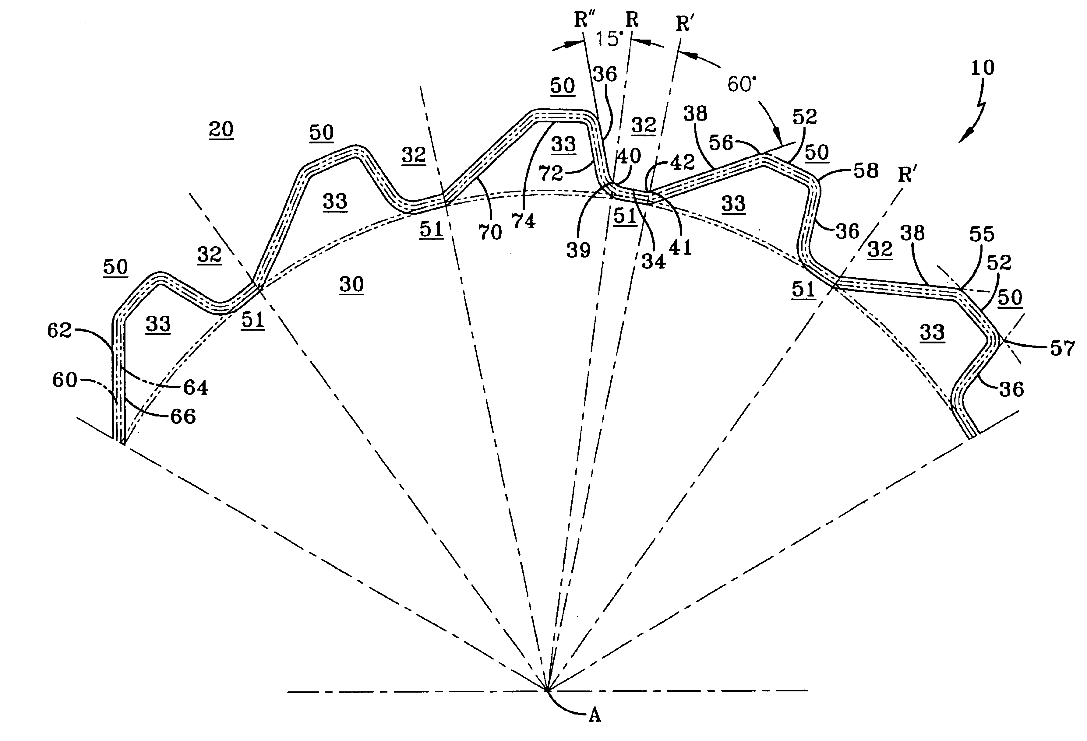
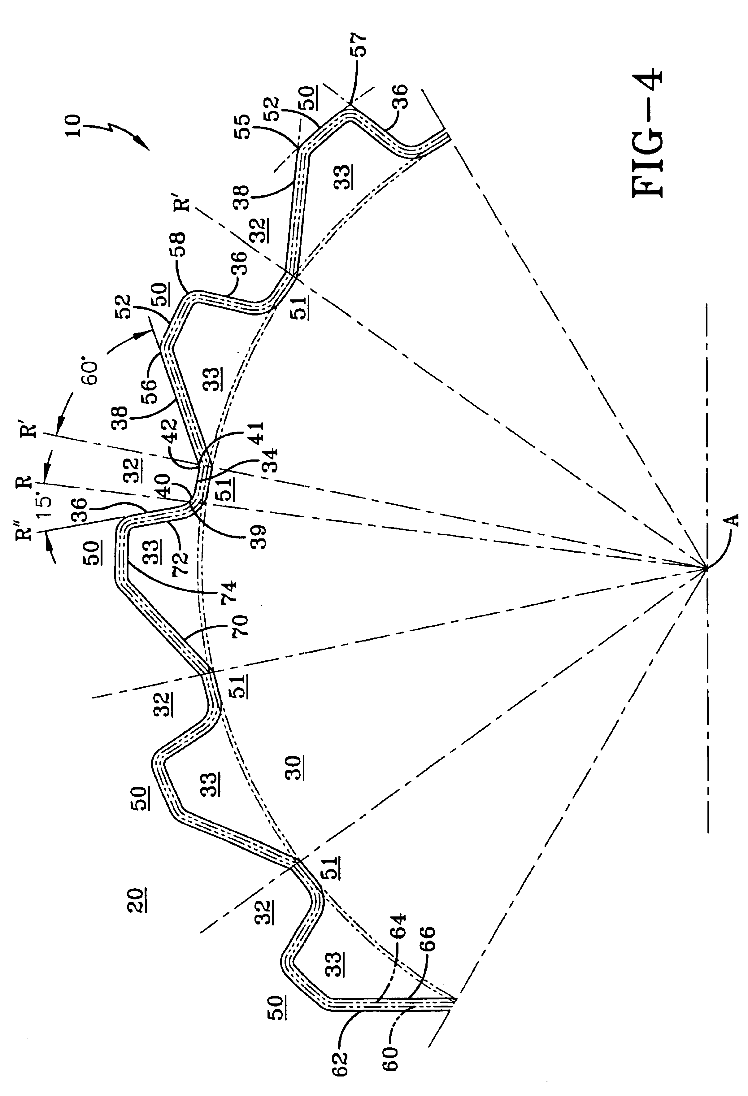
Referring now to the drawing wherein the showings are for the purpose of illustrating the preferred embodiment of the invention only, and not for purpose of limiting same, FIG. 4 shows the invention in a modification of one of its preferred forms. FIG. 4 shows a high torque system 10 comprised of an asymmetrical wrench 20 and a mating asymmetrical fastener 30 presented in an outline type form which could be an open or closed end wrench type. Standard wrenches and fasteners have a minimum and maximum cross flats dimension established by industry standards. These minimum and maximum dimensions require a maximum and minimum material. Wrench 20 has a maximum material 60 and a minimum required material 62. Fastener 30 has a maximum material 64 and a minimum material 66. The wrench and fastener must be within the minimum and maximum tolerances to be categorized within a specified head size.

FIGS. 4-8 show end views of preferred embodiments of fasteners and wrenches according to the inventi...


PUM


Abstract

A high torque wrenching system is provided having a wrench with asymmetrical torque transmission capability. The wrench includes a plurality of protuberances and a plurality of recesses around a central axis. The fastener also includes a plurality of protuberances and recesses around the central axis for mating with the wrench. The protuberances and recesses form a saw tooth shape. Each tooth or protuberance is formed by a first wrenching surface for loosening the fastener and a second wrenching surface for tightening the fastener. The wrenching surface carrying the loosening load will be at a much smaller angle, with respect to a radial vector extending from the wrench's central axis, than the wrenching surface carrying the tightening load. The result is that the loosening torque vector will have a much greater moment arm.

Description

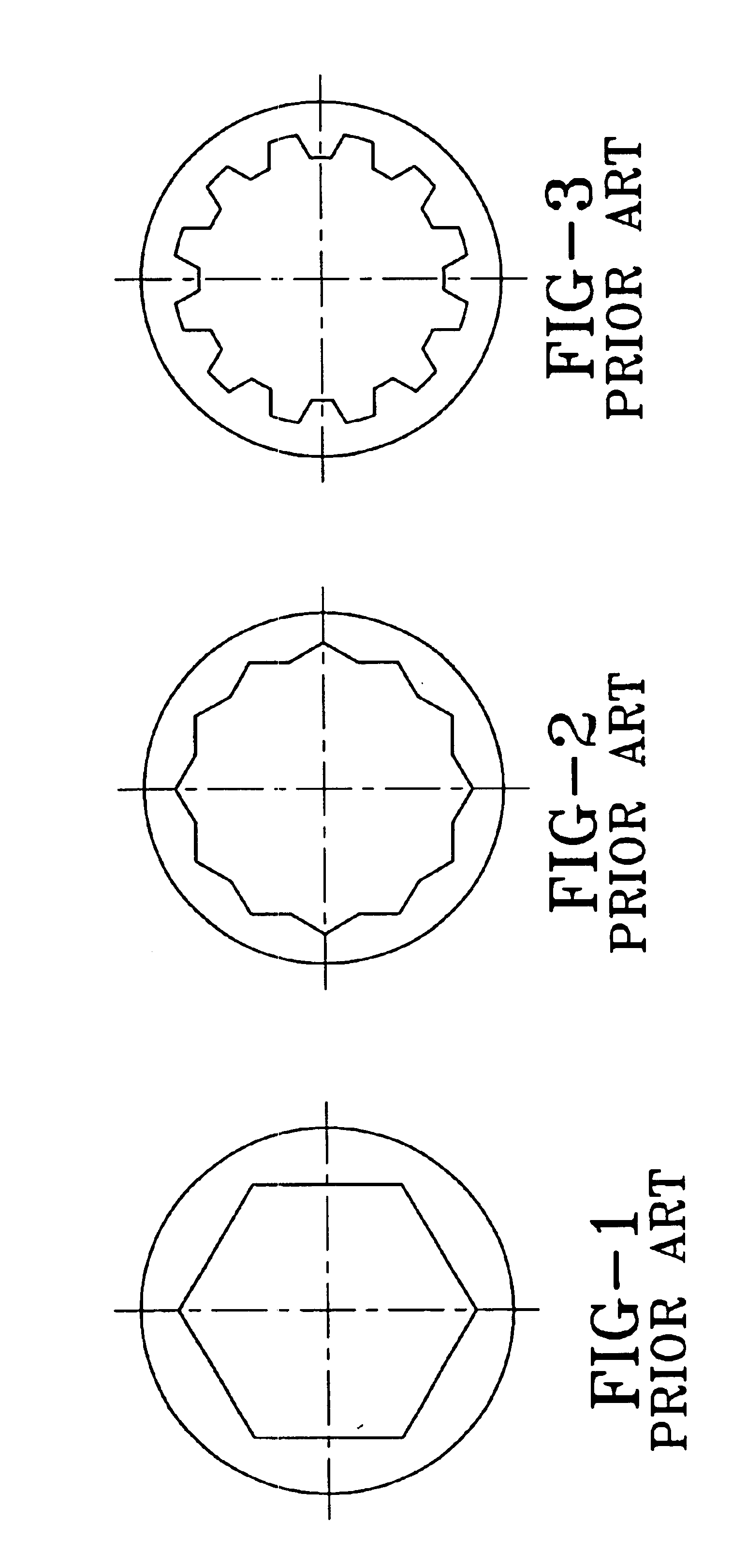
1. Field of the InventionThe invention relates generally to a wrench and fastener arrangement and more particularly to a wrench and fastener arrangement with driving surfaces that generate a higher torque in the loosening direction than in the tightening direction.2. Description of the Prior ArtWrenches and fasteners have been known in the art for some time. Current wrenches and the mating surfaces of fasteners have been designed symmetrically and have the property of transmitting torque equally in both the tightening and loosening directions. Typical socket wrench types of this kind are shown in FIGS. 1-3. FIG. 1 shows a 11 / 2" Hex socket, FIG. 2 shows a 1" 12 point socket, and FIG. 3 shows a 1" 12 point spline. However, the torque required for loosening a fastener that has been tightened is several times more than the torque required for tightening a fastener. This is because metal surfaces in contact with one another for an extended period of time tend to seize and resist separati...

Claims


Application Information

Patent Timeline
IPC IPC(8): B25B13/06B25B13/00B25B15/00F16B23/00
CPCB25B13/065B25B15/005F16B23/003F16B23/0061
Inventor WRIGHT, RICHARD B.
Owner WRIGHT TOOL
Why Eureka
Eureka Blog
Learn More