Rubber bearing for chassis parts in motor vehicles

a technology for chassis parts and rubber bearings, which is applied in the direction of bearings, sliding contact bearings, suspension arms with pips, etc., can solve the problems of difficult to achieve the required durability properties, many individual parts necessitate time-consuming assembly, and many individual parts require time-consuming assembly

Inactive Publication Date: 2004-03-09
BOGE ELASMETALL GMBH +1
View PDF7 Cites 13 Cited by
  • Summary
  • Abstract
  • Description
  • Claims
  • Application Information

AI Technical Summary

Benefits of technology

It is advantageous in this embodiment form that the intermediate part is connected with the elastomer body in a tightly adhering manner. This intermediate part comprises a metallic carrier with a fixedly adhering sliding coat at the inner circumferential surface. The actual material of the intermediate part is preferably produced from sheet steel, so that a surface treatment for the subsequent vulcanizing process, e.g., zinc coating, chrome coating or zinc / nickel coating with chromating, can be produced without a time-consuming covering of the inner sliding coat for pretreatment by sandblasting.
Assembly is simplified and facilitated as a whole because the rubber bearing can be produced as a permanent constructional unit. Further, the rubber bearing improves chassis comfort in motor vehicles because the elastic bearing which is free from restoring moment provides for better response of the individual chassis components so that, in turn, positive influences can be achieved for safety and driving dynamics. In this respect, it is especially advantageous when a rubber bearing of this type is used in highly practical, intelligent chassis components such as a variably adjustable vibration damper component.

Problems solved by technology

It is disadvantageous in this arrangement that the many individual parts necessitate time-consuming assembly in order to ready the entire rubber bearing for installation.
Moreover, due to the multiplicity of parts on the radial inner side of the elastomer body, it has turned out that in certain cases the required properties of durability can hardly be achieved or are difficult to achieve.
However, during operation of the rubber bearing the breakaway torque is very low during turning movement, so that a turning movement over 360.degree. can be achieved without a substantial restoring moment.

Method used


Image

  • Rubber bearing for chassis parts in motor vehicles
  • Rubber bearing for chassis parts in motor vehicles
  • Rubber bearing for chassis parts in motor vehicles

Examples


Embodiment Construction

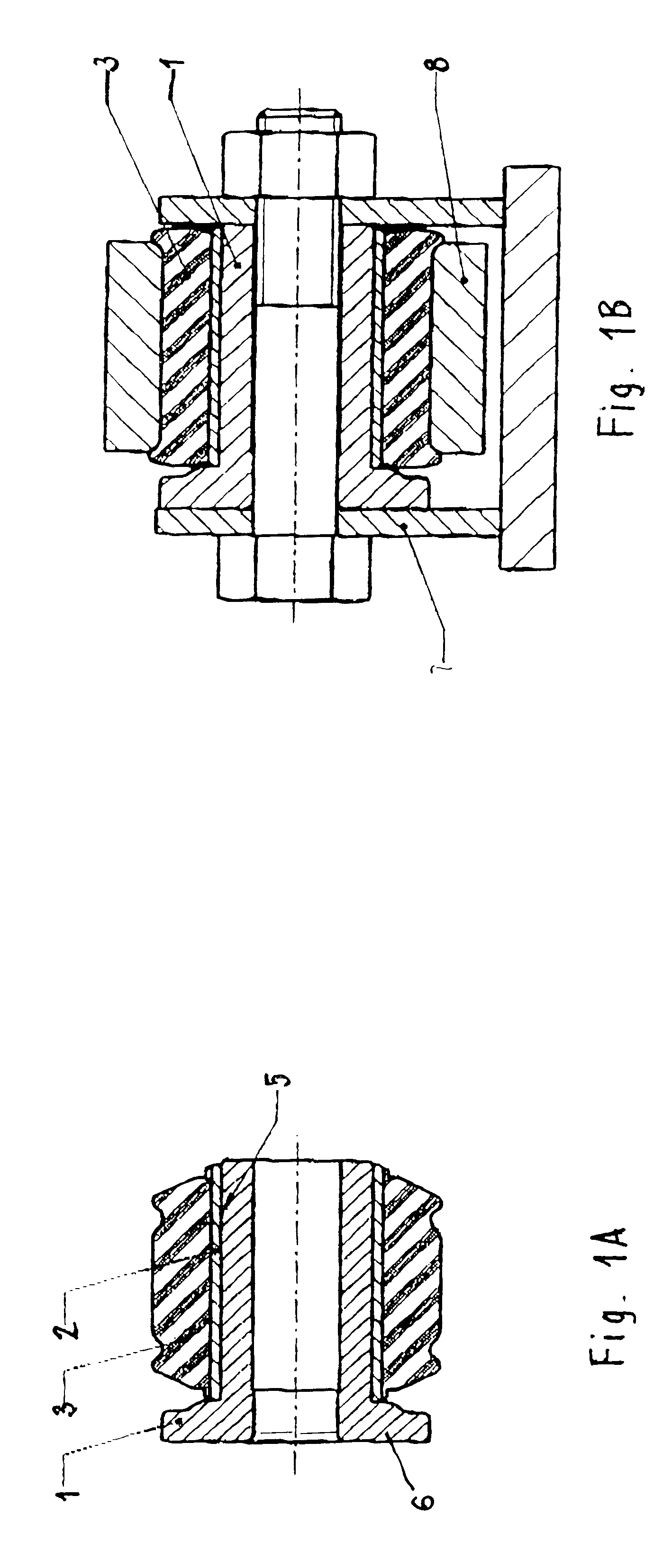
FIGS. 1A to 1B show a rubber bearing in which the inner tube 1 is enclosed by an intermediate tube 2 which is fixedly connected to the elastomer body 3. The sliding coat 5 is provided on the inner circumferential surface of the intermediate part 2. This rubber bearing is provided on one side with a radial shoulder 6 which serves as a stop for axial movements in the installed state. FIG. 1B shows the installed state in which the inner tube 1 is connected to a first vehicle part 7, while the elastomer body 3 is received directly in a receiving bore hole of a second vehicle part 8.

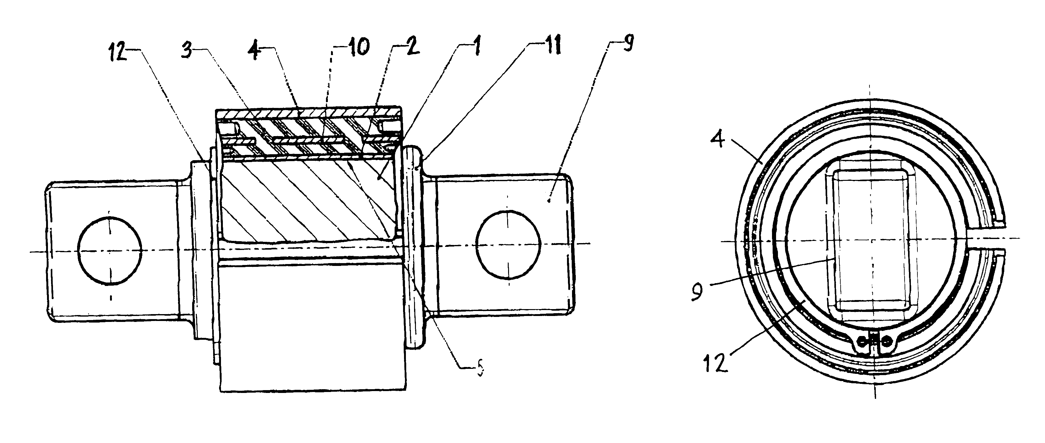
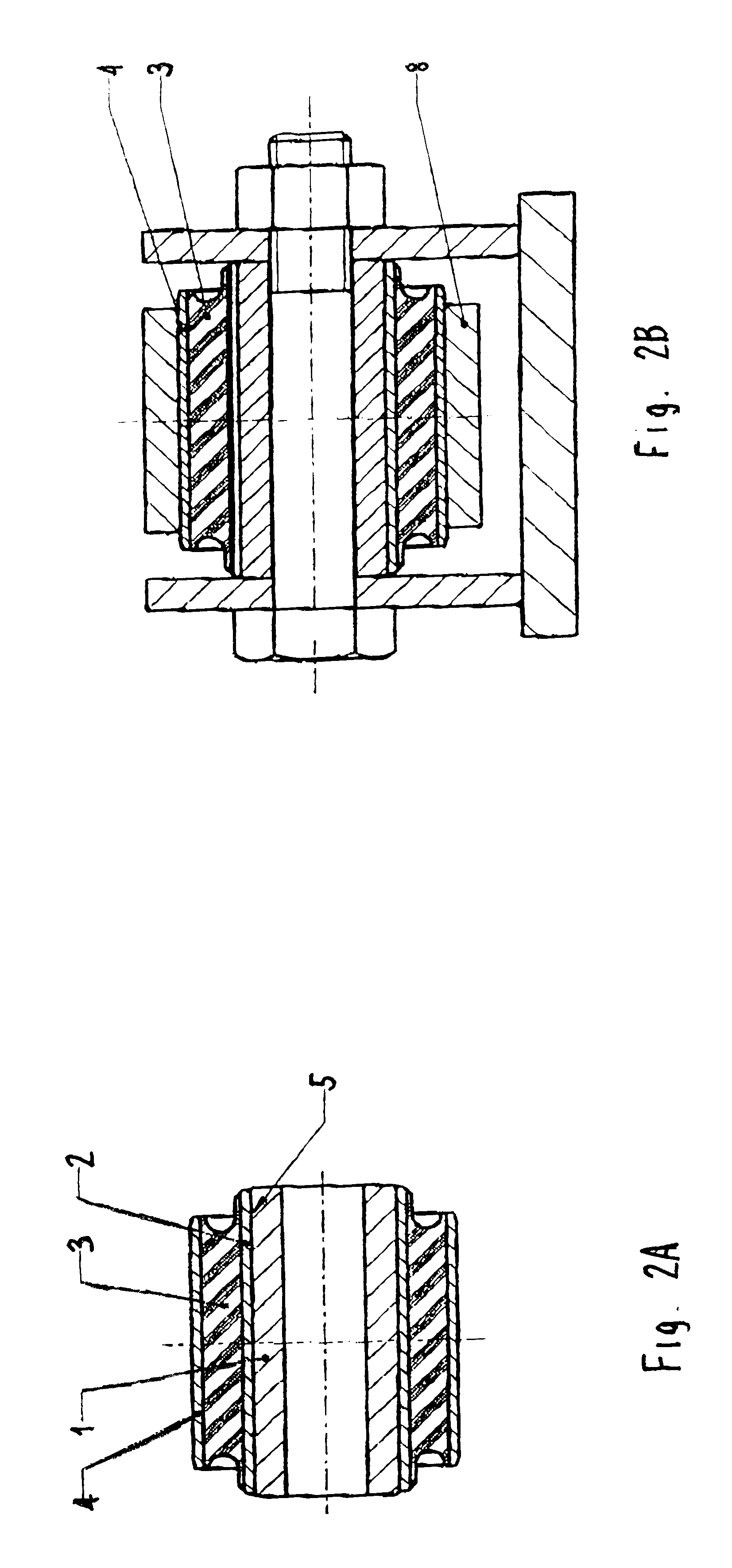
The rubber bearing shown in FIG. 2A comprises the inner tube 1 and the coating 5 which is arranged at the inner circumference of the intermediate part 2. The elastomer body 3 is enclosed coaxially by an outer tube 4. In the installed state according to FIG. 2B, the outer tube 4 is arranged in a receiving bore hole of a second vehicle part 8 by reducing the outer diameter. This increases the pretensioning in t...


PUM


Abstract

Rubber bearing for chassis parts in motor vehicles includes an inner tube which can be installed in a first chassis part, a concentrically arranged intermediate part which is slideably rotatable on said inner tube, an elastomeric body which surrounds and tightly adheres to the intermediate part and which can be installed in a second chassis part. The intermediate part which is fixedly connected with the elastomer body is provided with a sliding coat on its inner circumferential surface.

Description

1. Field of the InventionThe invention is directed to a rubber bearing for chassis parts in motor vehicles comprising an inner tube which can be installed in a first vehicle part, a concentrically arranged intermediate part which is rotatable so as to slide on the first vehicle part, an elastomer body which surrounds the intermediate part so as to adhere tightly to it and which can be installed in a second vehicle part and, if required, enclosed by an outer tube.2. Description of the Related ArtU.S. Pat. No. 5,593,233 discloses a rubber bearing for chassis parts in which the elastomer body is fastened to an outer tube and, in addition, a slide bushing made of a material having good sliding properties is received between the outer tube and the inner tube. The outer circumference of the elastomer body can be provided with another outer tube. It is disadvantageous in this arrangement that the many individual parts necessitate time-consuming assembly in order to ready the entire rubber ...

Claims


Application Information

Patent Timeline
Patent Type & Authority Patents(United States)
IPC IPC(8): B60G7/02F16C27/06F16F1/38F16C27/00
CPCB60G7/02F16C27/063F16F1/3842F16F2226/02F16C2326/05
Inventor TESTROET, MARTIN
Owner BOGE ELASMETALL GMBH
Why Eureka
Try Eureka