Capacity type pressure sensor and method of manufacturing the pressure sensor

a pressure sensor and capacity type technology, applied in the field of capacity type pressure sensors, can solve the problems of reducing the size of the pressure sensor frame 104 and undetectedly reducing the measurement sensitivity, so as to achieve the improvement of measurement sensitivity and the measurement range, and the distance between the upper and lower electrodes.

Inactive Publication Date: 2004-03-09
YAMATAKE HONEYWELL CO LTD
View PDF9 Cites 33 Cited by
  • Summary
  • Abstract
  • Description
  • Claims
  • Application Information

AI Technical Summary

Benefits of technology

With this arrangement, according to the present invention, the length of the pressure-sensing frame which elastically deforms upon application of a pressure can be maintained sufficiently large. Since the upper electrode is formed on the stage, the distance between the upper and lower electrodes can be decreased. Thus, the measurement sensitivity and the measurement range can be further improved.

Problems solved by technology

In the conventional example, however, when the electrode-to-electrode distance is decreased in an attempt to improve the measurement sensitivity, the pressure-sensing frame 104 is decreased in its size in the longitudinal direction and is not compressed easily, which undesirably decreases the measurement sensitivity.

Method used


Image

  • Capacity type pressure sensor and method of manufacturing the pressure sensor
  • Capacity type pressure sensor and method of manufacturing the pressure sensor
  • Capacity type pressure sensor and method of manufacturing the pressure sensor

Examples


Embodiment Construction

The present invention will be described in detail with reference to the drawings.

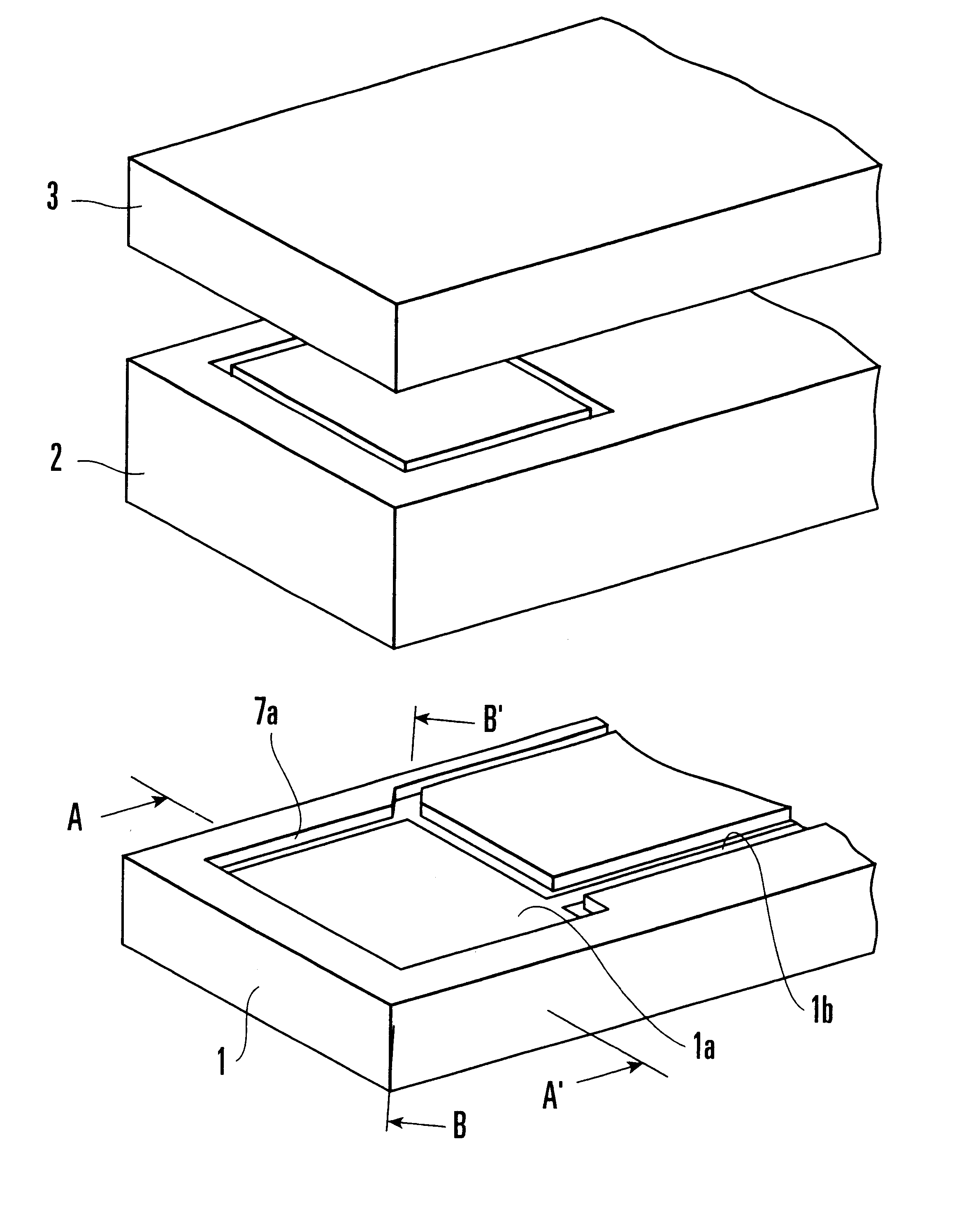
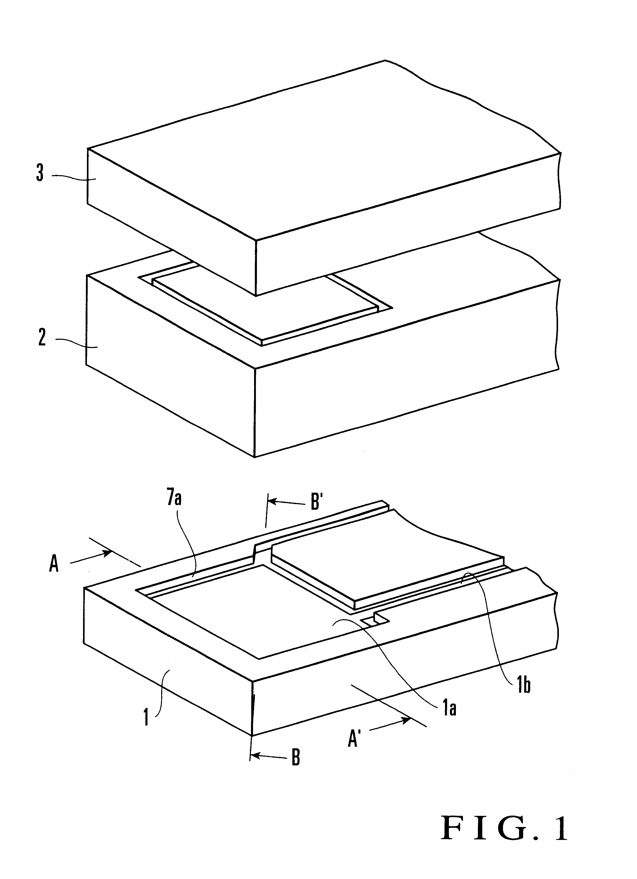
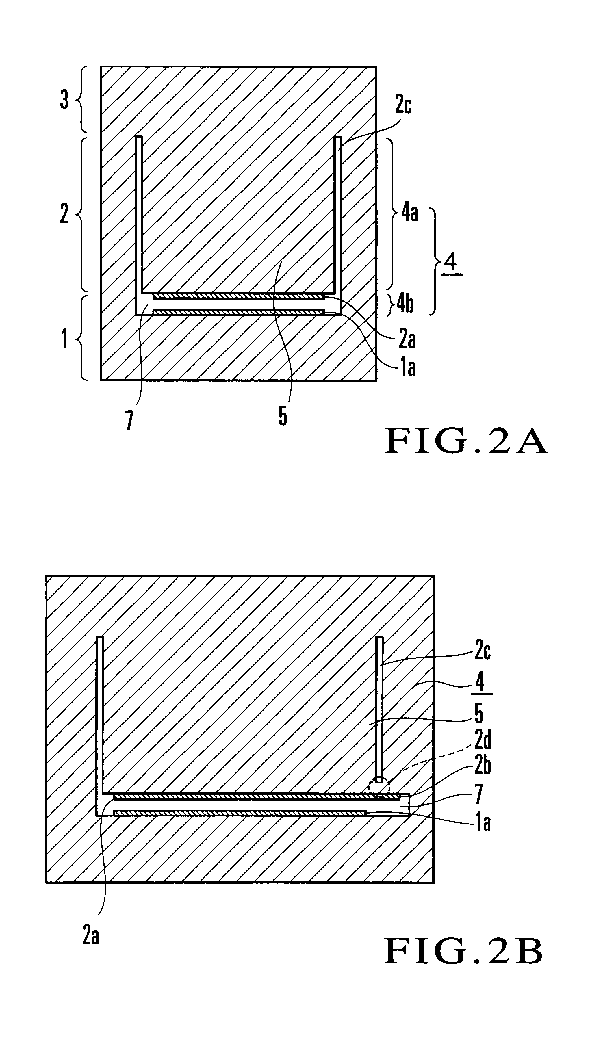
As shown in FIG. 1, a pressure sensor according to this embodiment is formed of a sapphire lower substrate 1 in which a rectangular lower electrode (stationary electrode) 1a and a lead wire 1b are formed in a recess 7a constituting a capacitance chamber 7 (FIGS. 2A and 2B), a sapphire intermediate substrate 2 having a substantially square upper electrode (movable electrode) 2a (FIGS. 2A and 2B) arranged in the capacitance chamber 7 to oppose the lower electrode 1a, and a slab-like upper substrate 3 bonded to the intermediate substrate 2. The lower surface of the intermediate substrate 2 is bonded to the upper surface of the lower substrate 1. The lower surface of the upper substrate 3 is bonded to the upper surface of the intermediate substrate 2.

As shown in FIG. 2A, the upper electrode 2a is formed on the lower surface of a region (to be referred to as a stage 5 hereinafter) partitioned by a groove 2c ...


PUM

PropertyMeasurementUnit
lengthaaaaaaaaaa
capacitanceaaaaaaaaaa

Abstract

A capacitive pressure sensor includes a first substrate (1), a first flat electrode (1a) formed on the first substrate (1), a pressure-sensing frame (4) surrounding the first flat electrode (1a) provided on the first substrate (1), second substrates (2, 3) connected to the pressure-sensing frame (4) opposedly to the first substrate (1) and forming a capacitance chamber (7) together with the first substrate (1) and the pressure-sensing frame (4), a stage (5) provided on the second substrates (2, 3) in the capacitance chamber (7), separated from the pressure-sensing frame (4), and opposed to and separated from the first flat electrode (1a), and a second flat electrode (2a) provided on the stage (5) and opposed to the first flat electrode (1a), wherein the pressure-sensing frame (4) deforms elastically according to a pressure applied to the first and second substrates (1, 2, 3).

Description

The present invention relates to a capacitive pressure sensor for detecting a change in capacitance (change in electrode-to-electrode distance) based on the deformation of a capacitance chamber caused by application of a pressure from the outside, and a method of manufacturing the same.In a conventional general capacitive pressure sensor, two opposing electrodes are arranged in a capacitance chamber surrounded by a flexible diaphragm and a base. With this arrangement, a change in electrode-to-electrode distance based on the elastic deformation of the diaphragm is detected as a change in capacitance, so that an external pressure applied to the diaphragm is measured.WO96 / 27123 (reference 1) proposes a pressure sensor based on an idea different from a conventional one. In the pressure sensor proposed by reference 1, a capacitance chamber is formed in an elastic substrate made of sapphire or the like, and two opposing electrodes are arranged in the capacitance chamber. With this arrange...

Claims


Application Information

Patent Timeline
Patent Type & Authority Patents(United States)
IPC IPC(8): H01G5/00H01G4/38H01G5/16G01D5/241G01L9/00G01L9/12H01G5/014H01L29/84
CPCG01D5/2417G01L9/0075H01G5/014H01G5/16
Inventor ISHIKURA, YOSHIYUKI
Owner YAMATAKE HONEYWELL CO LTD
Why Eureka
Try Eureka