

Modified rope tensioner
a technology of tensioner and rope, which is applied in the direction of vehicle/pulley rope, washing apparatus, cables, etc., can solve the problems of difficult to achieve the correct tension installation of the rope, time-consuming and often difficult process of placing the turnbuckle in the rope, and operator injury
- Summary
- Abstract
- Description
- Claims
- Application Information
AI Technical Summary
Benefits of technology
Problems solved by technology
Method used
Image

Examples
Embodiment Construction
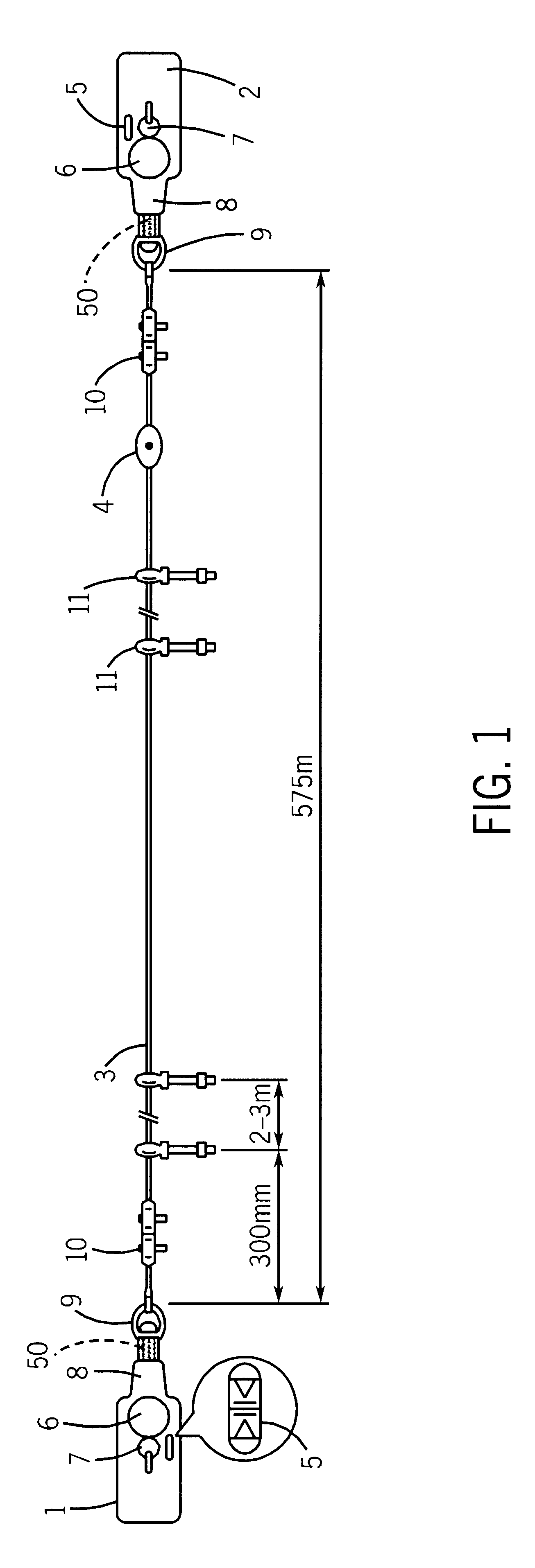
Referring to FIG. 1 of the accompanying drawings, there is illustrated a rope operated switch assembly comprising a first switch 1, a second switch 2, a rope 3 extending between the switches and a tensioner 4 installed along the rope.
The switches 1 and 2 are of any suitable design, and may be as described in WO-A-97 / 20334, for example. The switches are such that two tension thresholds are established. The first, lower threshold is such that unless the tension of the rope exceeds the first threshold the switch cuts off the supply of power required to enable the machinery to be operated. The second, higher threshold is such that unless the tension on the rope is less than the second threshold, the switch again acts to cut off the supply of power to the machinery. The switches 1, 2 each comprise a tension indicator 5, an emergency stop button 6, and a reset knob 7. Each switch also comprises a tubular body extension 8 which receives a spring-loaded shaft 50 (shown in phantom) attached ...
PUM
 Abstract
Description
Claims
Application Information