Eureka AIR delivers breakthrough ideas for toughest innovation challenges, trusted by R&D personnel around the world.

Drilling with casing

Inactive Publication Date: 2004-03-16
SCHLUMBERGER TECH CORP
View PDF27 Cites 114 Cited by
  • Summary
  • Abstract
  • Description
  • Claims
  • Application Information

AI Technical Summary

Problems solved by technology

This conventional system which requires sequentially drilling the borehole using drill pipe with a drill bit attached thereto, pulling the drill pipe out of the borehole and running casing into the borehole is time consuming and costly.
In addition, control of the well is difficult during the period that the drill pipe is being removed and the casing is being run in.
No system is currently available for drilling directional boreholes using casing.
When directional drilling, companies must accept the increased cost, time and hazard of separately drilling and then lining a borehole.

Method used


Image

  • Drilling with casing
  • Drilling with casing
  • Drilling with casing

Examples


Embodiment Construction

The drawing figures that follow are not necessarily to scale, and certain features are shown in generalized form in the interests of clarity.

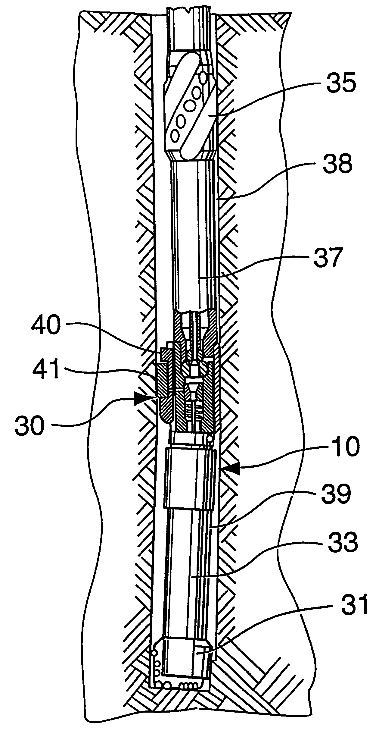
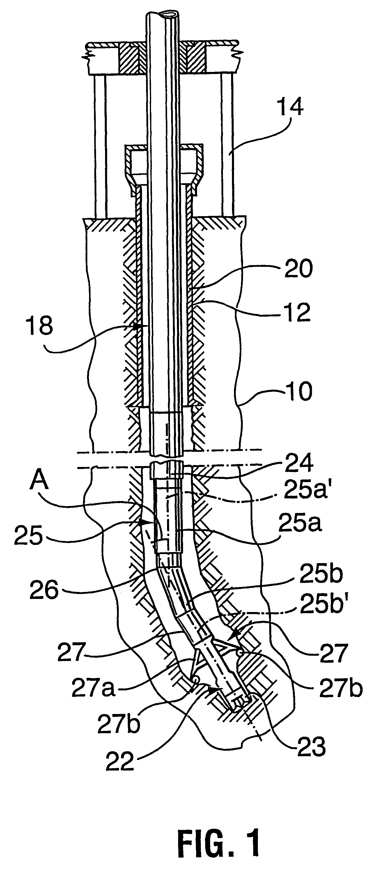
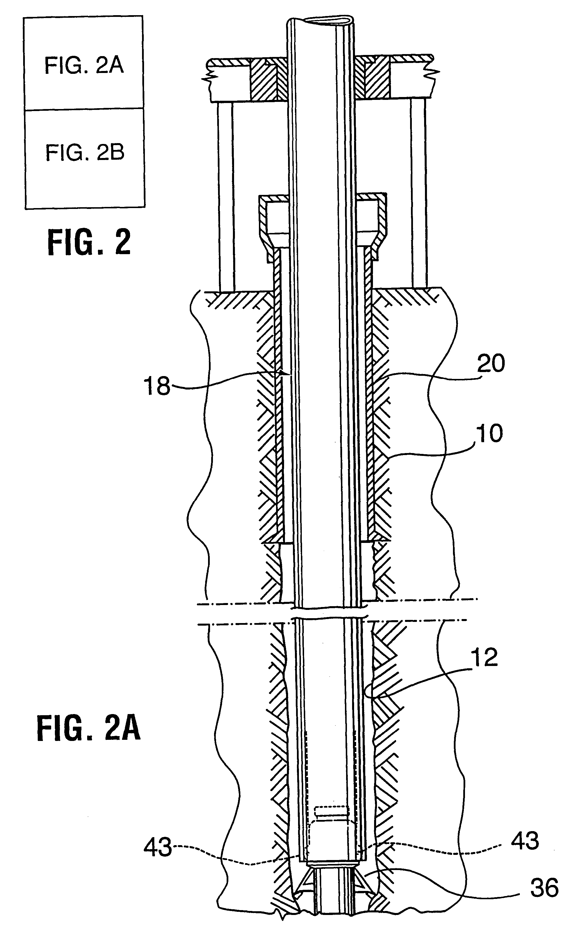
FIG. 1 refers to an embodiment using a mud motor having a bent housing. There is illustrated an earth formation 10 into which a wellbore 12 is being formed by a casing drilling assembly and using a method in accordance with the present invention. Wellbore 12 is formed by a rig 14 (only shown in part) including a top drive (not shown) and a casing string, generally indicated at 18. Casing string 18 is made up of joints of pipe threaded together end to end using, for example, conventional casing threads or high strength threads. Wellbore 12 is shown with a larger diameter casing string 20 cemented to the earth formation 10. The smaller diameter casing string 18 extends through casing string 20 and is used for drilling the wellbore.

Wellbore 12 is being formed in accordance with the present invention by a bit assembly 22 and a mud motor 25 connecte...


PUM


Abstract

A method and apparatus for drilling directional wellbores using a casing string as a drill stem is taught. A retrievable bit is mounted at an end of the casing string and either a mud motor with a bent housing and / or bent sub or a rotary steerable tool is used to direct the bit to drill directionally.

Description

This invention is directed to well drilling and, in particular, to processes and devices for well drilling wherein a wellbore is advanced with a drill bit affixed to the distal end of a casing string.BACKGROUND OF THE ARTThe drilling of wells, for example, for oil and gas production conventionally employs relatively small diameter strings of drill pipe to which is secured a drill bit of somewhat larger diameter. After a selected portion of the wellbore has been drilled, the well bore is usually lined with a string of tubulars known as casing. The casing (herein used to encompass any wellbore liner) has a larger diameter than drill pipe and a smaller diameter than the drill bit. This conventional system which requires sequentially drilling the borehole using drill pipe with a drill bit attached thereto, pulling the drill pipe out of the borehole and running casing into the borehole is time consuming and costly. In addition, control of the well is difficult during the period that the ...

Claims


Application Information

Patent Timeline
IPC IPC(8): E21B7/06E21B7/04E21B7/20E21B10/00E21B10/66
CPCE21B7/067E21B7/208E21B10/66
Inventor TESSARI, ROBERT M.
Owner SCHLUMBERGER TECH CORP
Why Eureka
Eureka Blog
Learn More