Integrated magnetic bearing

a magnetic bearing and integral technology, applied in the direction of mechanical energy handling, dynamo-electric components, mechanical apparatus, etc., can solve the problems of unwanted detent torque within the actuator, increased difficulty in accurate pointing, and potential for significant cross coupling effects

Inactive Publication Date: 2004-03-16
AIREX CORP
View PDF11 Cites 112 Cited by
  • Summary
  • Abstract
  • Description
  • Claims
  • Application Information

AI Technical Summary

Problems solved by technology

Note that each of these designs is toothed, which creates unwanted detent torque within the actuator and makes accurate pointing more difficult.
The most significant design issues for both AC and DC combination motor-bearings are reducing the detrimental effects of magnetic flux cross coupling upon the motoring and bearing control actions, and achieving target force and torque specifications.
This design efficiency, however, creates potential for significant cross coupling effects that must be carefully treated.

Method used


Image

  • Integrated magnetic bearing
  • Integrated magnetic bearing
  • Integrated magnetic bearing

Examples


Embodiment Construction

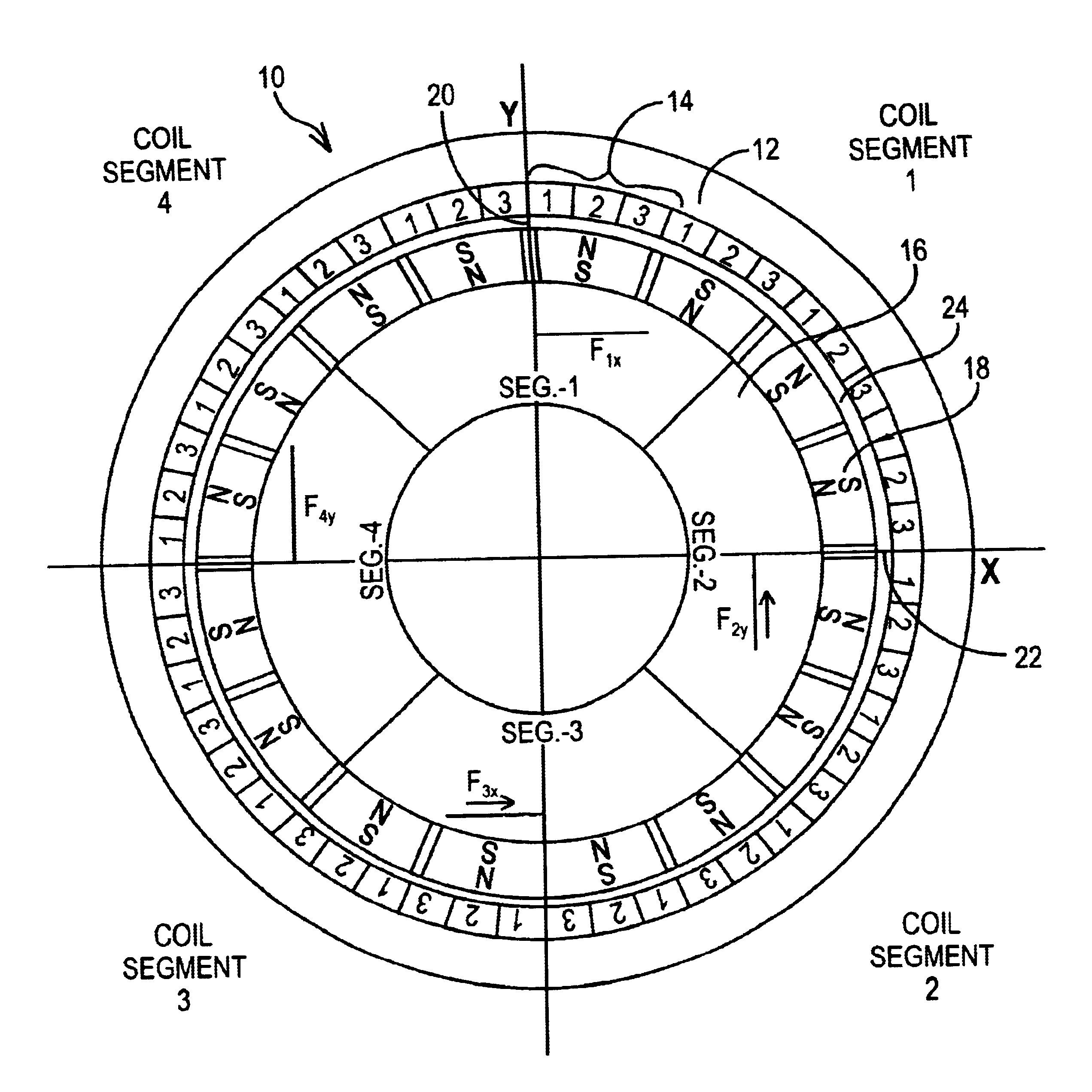
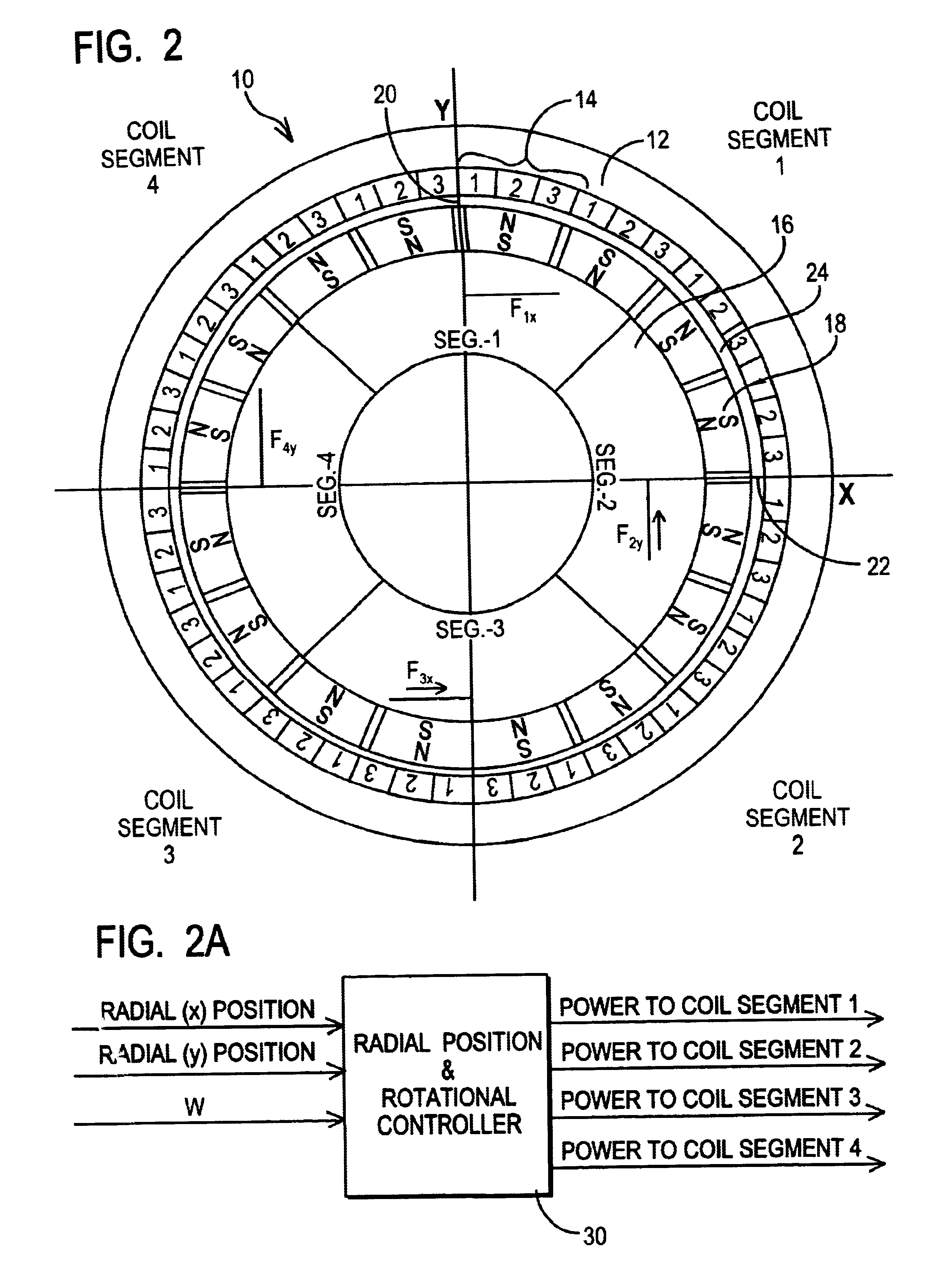
FIG. 2 depicts an integrated magnetic bearing and toothless DC brushless motor 10 according to one exemplary embodiment of the present invention. In the present exemplary embodiment, the integrated motor 10 includes a generally circular stator 12 that includes a plurality of coil phases 14 arranged around the inner periphery of the stator. Depicted in FIG. 2 is a plurality of coil segments, each containing coils, wherein each coil segment comprises any number of phases (at least two), and the exemplary arrangement illustrated is a three-phase arrangement, i.e., phase 1, 2 and 3. The present invention equally contemplates other phase numbers, and should be generally and broadly construed as any polyphase coil arrangement. The motor also includes a rotor 16 that has a plurality of permanent magnets 18 placed along the outer periphery of the rotor, and magnetic coupled to the coils. The magnets are magnetized in alternating north and south polarity in the radial direction. A clearance ...


PUM


Abstract

The present invention provides a rotational magnetic gimbal with an integral magnetic bearing. Brushless DC motor technology provides electromagnetic suspension, using a single electromagnetic actuator to perform both the radial bearing and rotary torque (motoring) functions. An integrated motor and magnetic bearing consistent with the invention comprises a rotor comprising a plurality of permanent magnets and a stator comprising a plurality of independently controlled coil segments magnetically coupled to the permanent magnets. Embodiments may further comprise first and second radial position sensors, the first radial position sensor disposed in or adjacent to a clearance gap between the rotor and the stator for sensing the position of the rotor with respect to the stator along a first axis, and a second radial position sensor disposed in or adjacent to the clearance gap between the rotor and the stator for sensing the position of the rotor with respect to the stator along a second axis. In method form, a method for providing integral electromagnetic motor and bearing functions comprises sensing a first radial position of a rotor, the rotor comprising a plurality of permanent magnets, with respect to a stator along a first axis, the stator comprising a plurality of independently controlled coil segments magnetically coupled to the permanent magnets; and sensing a second radial position of the rotor with respect to the stator along a second axis; and delivering current to at least one coil segment, the amount of current based on at least one sensed position.

Description

1. Field of the InventionThe present invention relates generally to a rotational magnetic gimbal with an integral magnetic bearing. More particularly, the present invention relates to brushless DC motor technology that provides electromagnetic suspension, using a single electromagnetic actuator to perform both the bearing and rotary torque (motoring) functions.2. Description of Related ArtCurrent rotational electric motors employ mechanical bearings in their ends or on the apparatus to which they are providing torque. Recent research in the area of combination motor-bearings has yielded working prototypes of both AC and DC machines. Although some AC machines can provide rotational positioning, more commonly these machines find application where a constant rotating speed is required in spite of load variations. The primary benefit is the potential for high power density and high-speed machines due to the smaller size (length / volume) of combination motor-bearings. Prototypes of AC typ...

Claims


Application Information

Patent Timeline
Patent Type & Authority Patents(United States)
IPC IPC(8): F16C39/06F16C39/00H02K7/09
CPCF16C32/0493H02K7/09F16C32/0497F16C2380/26
Inventor CARROLL, DAVIDSEDGEWICK, JAMES
Owner AIREX CORP
Why Eureka
Try Eureka