Pipe structure of branch pipe line

a branch pipe and pipe structure technology, applied in the direction of liquid/fluent solid measurement, volume/mass flow by differential pressure, instruments, etc., can solve the problem of elbow joint cracking and other problems

Inactive Publication Date: 2004-03-23
MITSUBISHI HEAVY IND LTD
View PDF25 Cites 9 Cited by
  • Summary
  • Abstract
  • Description
  • Claims
  • Application Information

AI Technical Summary

Benefits of technology

The invention is directed to solve the above-described problem of the prior art, and to provide a piping arrangement of a branch pipe for avoiding adverse effect to the piping system, based on a thermal stratification generated by a cavity flow in the closed branch pipe.

Problems solved by technology

If a thermal stratification appears in a pipe, in particular in an elbow joint of the piping system, a crack may be resulted in the elbow joint due to the thermal stress in the elbow joint.

Method used


Image

  • Pipe structure of branch pipe line
  • Pipe structure of branch pipe line
  • Pipe structure of branch pipe line

Examples


Embodiment Construction

A various preferred embodiments of the invention will be described below with reference to the accompanying drawings.

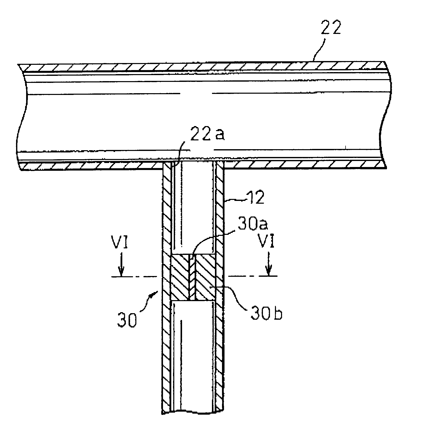
With reference to FIG. 11, a piping system to which the present invention is applied is shown. In FIG. 11, a branch pipe 10 is connected to a main pipe 22, providing a water main line (hereinafter, referred to main pipe 22), at a junction 22a. The branch pipe 10 has a cross pipe 12 and a horizontal pipe 14 connected to the cross pipe 12 by an elbow joint 14, and forms a closed branch pipe when a valve 20, provided in an extended portion 18 of the horizontal pipe 14, is closed. The extended portion 18 is not limited to the horizontal configuration.

In a large plant such as an electric power plant, a number of branch pipes are connected to a main pipe. Some of the branch pipes are used during only maintenance or the starting operation of the plant, and are not used during the normal operation of the plant with the valves on the branch pipes closed after the plant is star...


PUM


Abstract

A water pipe structure of a branch pipe line (12) connected to a main pipe (22) for flowing water therethrough, wherein a cavity flow suppressing structure (30) is installed between the main pipe (22) and the branch pipe line (12) or in the branch pipe line to suppress a cavity flow produced in the closed branch pipeline, whereby the adverse effect of a thermal stratification formed by the cavity flow on the pipe can be eliminated.

Description

The invention relates to a water piping arrangement, and in particular to a water piping arrangement for avoiding adverse effect to the piping system based on a thermal stratification which is formed by a cavity flow which is generated in a closed pipe branched from a main pipeDESCRIPTION OF THE PRIOR ARTA various branch pipes are generally connected to a main water pipe in a power plant or the other types of plant, in which some branch pipes are used during only the starting operation or the maintenance of the plant and closed by a shut-off valve provided in the branch pipes after the operation of the plant is transferred to a normal operation.The inventors of the present application have found that such a branch pipe closed by a shut-off valve (hereinafter, referred to a closed branch pipe) functions as a deep recess formed in a main pipe, and that, within the closed branch pipe, a cavity flow is induced by the water flow in the main pipe. If the cavity flow is affected by a heat ...

Claims


Application Information

Patent Timeline
Patent Type & Authority Patents(United States)
IPC IPC(8): E03C1/02F15D1/02F15D1/00F16L55/027F16L55/02F16L41/02F16L55/00F17D1/20
CPCF16L55/02718E03C1/023F15D1/02F16L55/027Y10T137/85938F16L41/02
Inventor SHIRAISHI, TADASHINABIKA, YUKIHARUSUZUKI, SHIGEKI
Owner MITSUBISHI HEAVY IND LTD
Why Eureka
Try Eureka