Float collar

a technology of float collars and float plates, which is applied in the direction of drilling casings, drilling pipes, and accessories for wellbores. it can solve the problems of wasting valuable time and resources, and affecting the drilling effect of the float collar assembly

Inactive Publication Date: 2004-03-30
ALLAMON JERRY P +2
View PDF9 Cites 76 Cited by
  • Summary
  • Abstract
  • Description
  • Claims
  • Application Information

AI Technical Summary

Benefits of technology

Furthermore, while components of prior art float collars are fabricated almost entirely from metal, the float collar apparatus of the present invention is fabricated from a combination of metal and non-metal components, or from non-metal components only. This resultant float collar assembly provides a savings in time and resources expended during drilling out of the float collar.

Problems solved by technology

While prior art float collars have produced desirable results for the oil well industry, an undesirable feature of prior art float collars is that once cementing operations are complete, prior art float collars require approximately six hours to drill out of the casing liner to reestablish the unobstructed flow path.
This relatively long drill out time is due in large part to the high metal content of components of the float collar.
While the use of such metals allows the float collar assembly to be set at pressures up to 3000 psi, the metal components of the float collar assembly become a disadvantage when cementing operations are completed and valuable time and resources must be expended during drilling out the float collar.

Method used


Image

  • Float collar
  • Float collar
  • Float collar

Examples


first embodiment

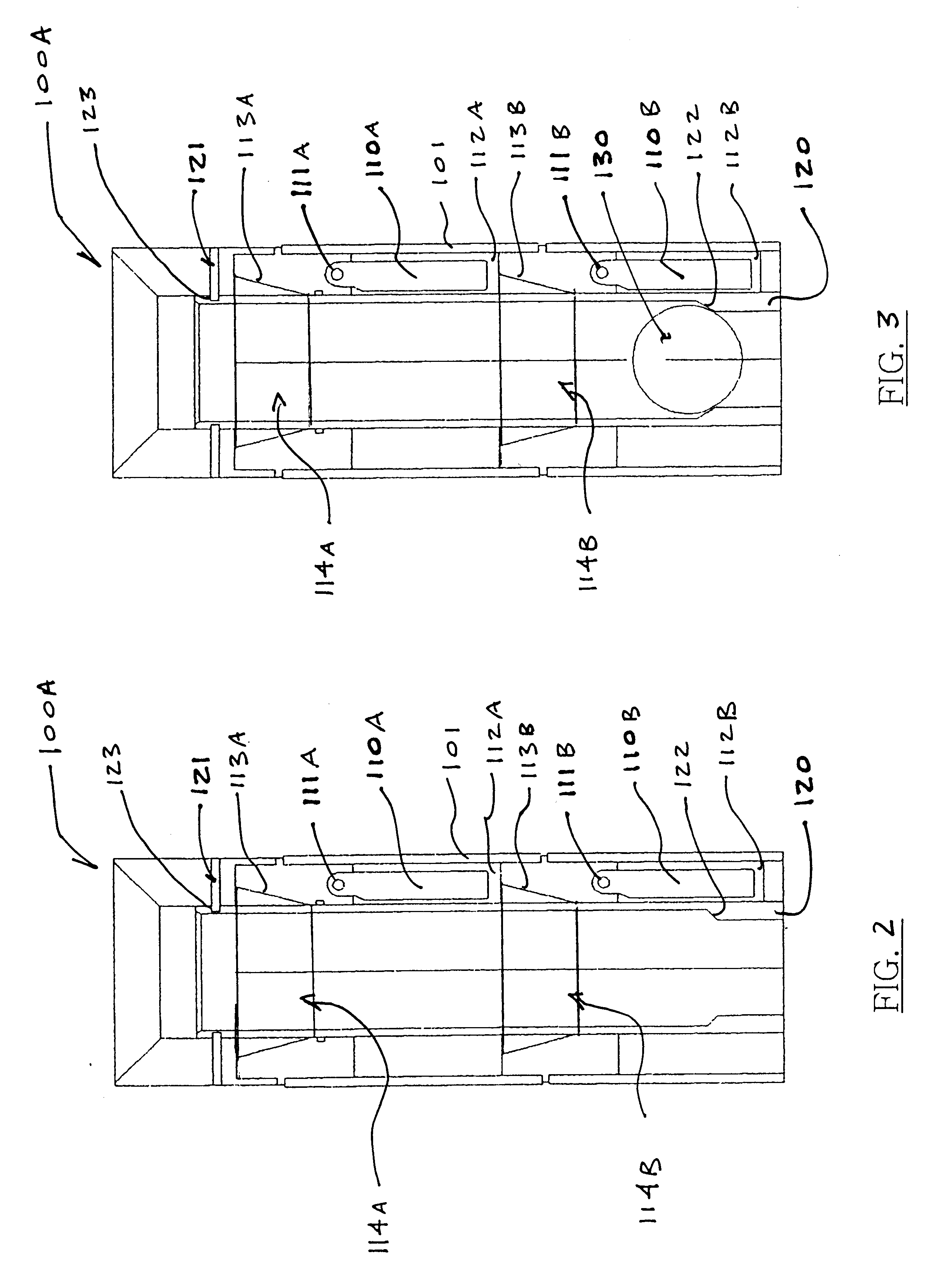
With reference to FIG. 2, a float collar assembly 100A in accordance with the present invention includes a housing 101, two flapper valve assemblies 114A, 114B, and a valve-actuating sleeve 120. Each flapper valve assembly 114A, 114B includes a flapper 110A, 110B, a flapper recess 112A, 112B, a pin and spring 111A, 111B, and a frustoconical valve body 113A, 113B. The actuating sleeve 120 includes a drop ball seat 122 integral with the inner surface of the actuating sleeve and having an axial bore therethrough for receiving a drop ball 130 (FIG. 3). The diameter of the drop ball 130 (FIG. 3) is less than or equal to diameter of the actuating sleeve 120, but greater than diameter of the axial bore of the drop ball seat 122. Additionally, the actuating sleeve 120 includes a plurality of pin recesses 123 for receiving a plurality of shear pins 121. The pin recesses 123 are formed along the outer surface and near the upper end of the actuating sleeve 120.

Still with reference to FIG. 2, i...

second embodiment

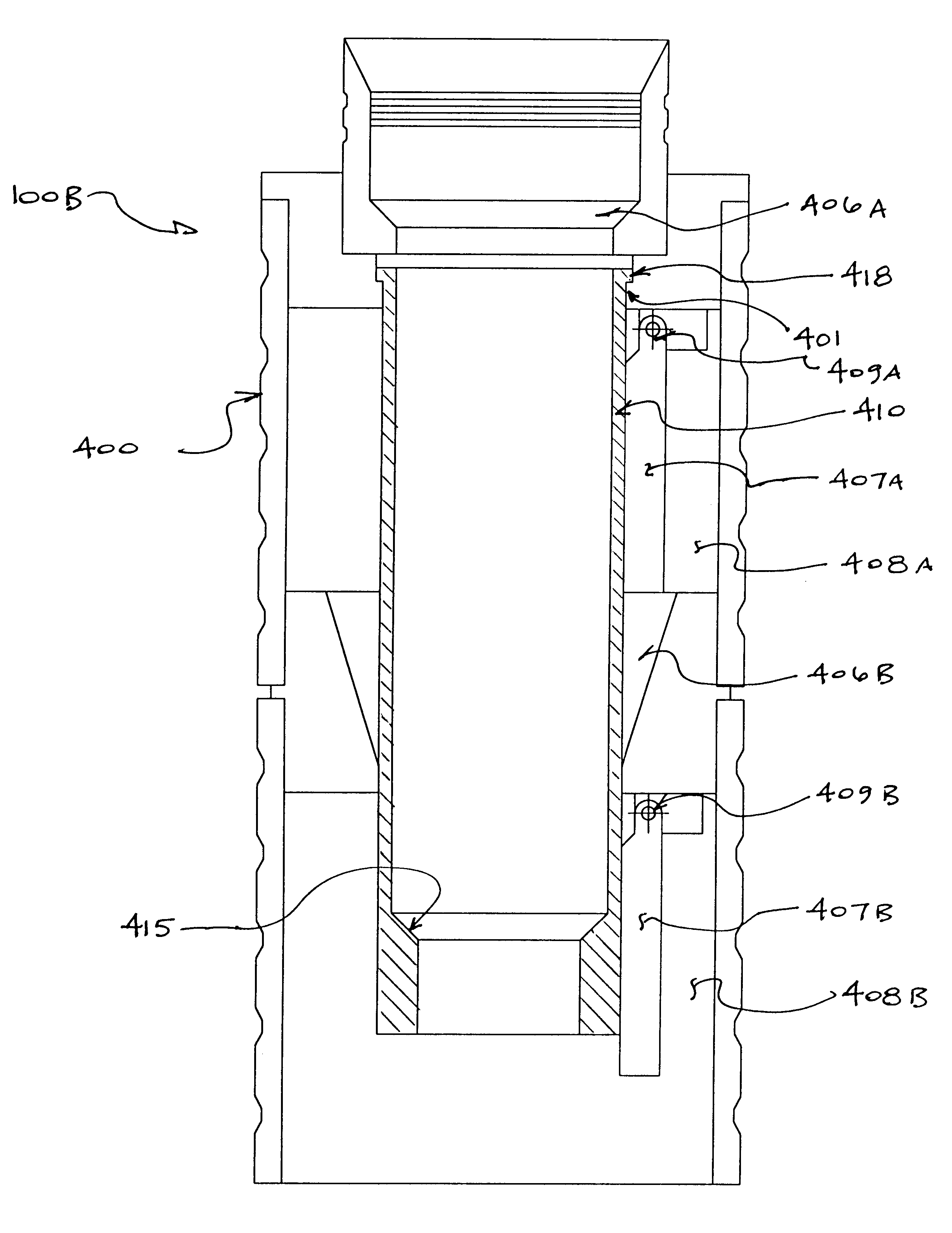
With reference to FIG. 5, a float collar assembly 100B in accordance with the present invention comprises a housing 400, two flapper valve assemblies, and a valve-actuating sleeve 410. Each flapper valve assembly comprises a flapper 407A, 407B, a flapper recess 408A, 408B, a pin and spring 409A, 409B, and a frustoconical valve body 406A, 406B. The actuating sleeve 410 comprises a drop ball seat 415 being integral with the inner surface of the actuating sleeve and having an axial bore therethrough for receiving a drop ball 420 (FIGS. 6A-6C). The diameter of the drop ball 420 (FIGS. 6A-6C) is less than or equal to diameter of the actuating sleeve 410, but greater than diameter of the axial bore of the drop ball seat 415. Additionally, the actuating sleeve 420 comprises a shoulder 418 protruding radially outward for engaging with a groove 401 formed in the housing 400 and protruding radially inward. The shoulder 418 is formed near the upper end of the actuating sleeve 420.

With referenc...


PUM


Abstract

The present invention relates to a float collar apparatus for regulating the passage of fluid through a drilling / production liner or sub-sea casing. Apparatus of the present invention is fabricated using plastic flapper valves and valve-actuating sleeve components in contrast to prior art float collar components which are fabricated almost entirely of hard metals. Particularly, the plastic may be nylon, phenolic, or a phenolic-nylon laminate. The use of plastic components in the float collar apparatus of the present invention provides a substantial reduction in time and resources expended during drilling out of the float collar once cementing operations are completed. Additionally, the float collar apparatus of the present invention is fabricated from a pre-determined combination of plastic components and metal components thereby ensuring that the improved float collar can still endure substantial hydrostatic stresses encountered during casing liner running in and cementing operations.

Description

1. Field of the InventionThe present invention relates to apparatus for use in the oil industry, and, more particularly, to a float collar apparatus for use in oil well drilling operations.2. Description of the Prior ArtFloat collars are utilized by the oil well industry with respect to operations for running in and cementing casing liners down a wellbore. An example of a prior art float collar is the Multi-Purpose Float Collar manufactured and sold by Davis-Lynch, Inc. The Multi-Purpose Float Collar comprises a tubular housing having a bore therethrough and two spring-activated flapper valves which are held in an open position by a sliding sleeve installed in the bore of the float collar. Once the sleeve is forced out of the bore of the float collar, the spring-activated flapper valves are free to rotate to their closed positions.In practice, a float collar, such as the Multi-Purpose Float Collar of Davis-Lynch, Inc., is installed within the lower end of a casing liner prior to run...

Claims


Application Information

Patent Timeline
Patent Type & Authority Patents(United States)
IPC IPC(8): E21B21/00E21B21/10
CPCE21B21/10
Inventor ALLAMON, JERRY P.
Owner ALLAMON JERRY P
Why Eureka
Try Eureka