Connecting device for profiled bars with grooves

a technology of connecting device and profiled bar, which is applied in the direction of rod connection, large fixed member, building scaffold, etc., can solve the problem that the plate connector is not able to ensure the connection of the grooves in the individual profiles

Inactive Publication Date: 2004-03-30
FMS FORDER UND MONTAGE SYST SCHMALZHOFER
View PDF17 Cites 131 Cited by
  • Summary
  • Abstract
  • Description
  • Claims
  • Application Information

AI Technical Summary

Problems solved by technology

A large number of exemplary embodiments for producing a connection between profiled bars with grooves, using a plate connector, are known, but they have the

Method used


Image

  • Connecting device for profiled bars with grooves
  • Connecting device for profiled bars with grooves
  • Connecting device for profiled bars with grooves

Examples


Embodiment Construction

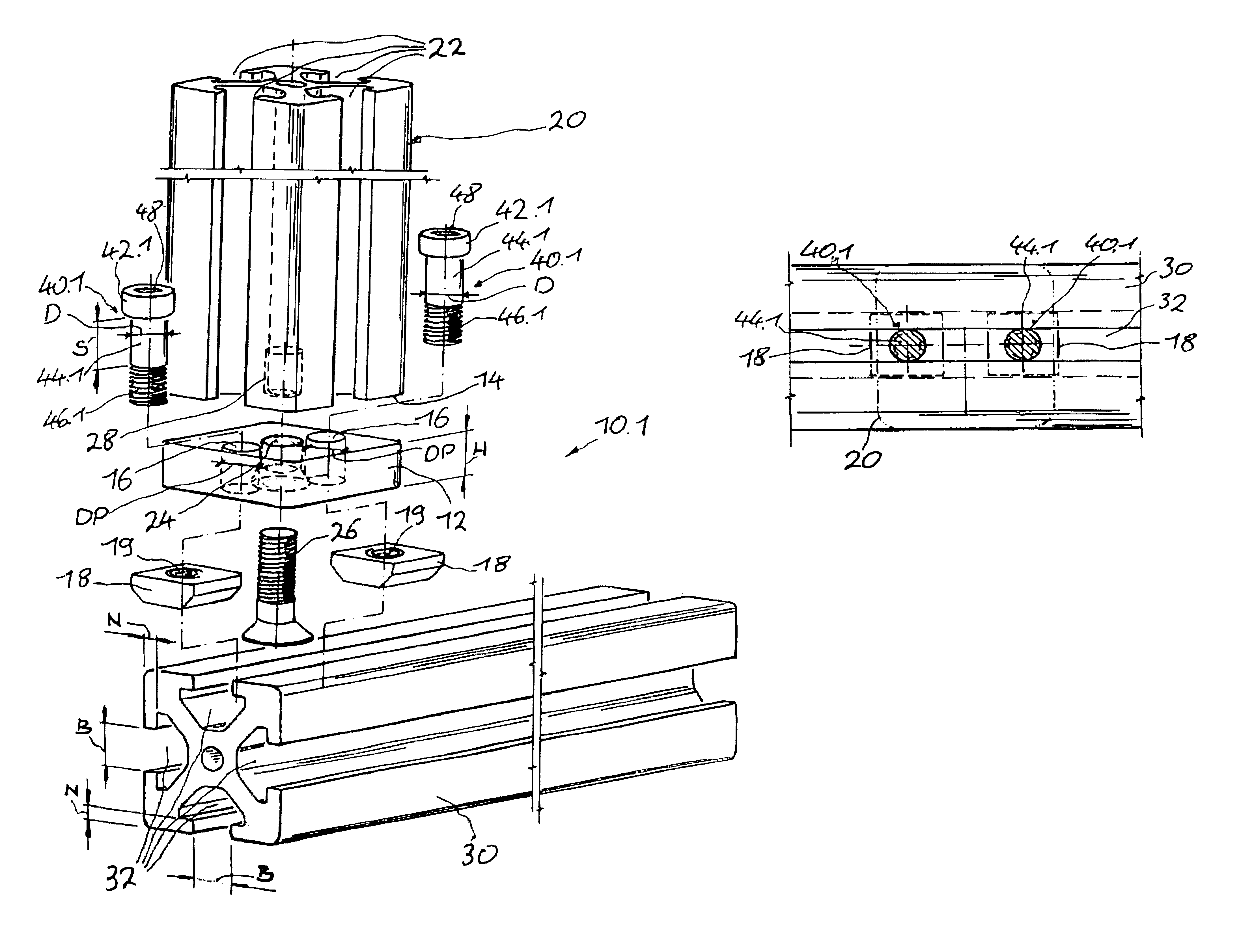
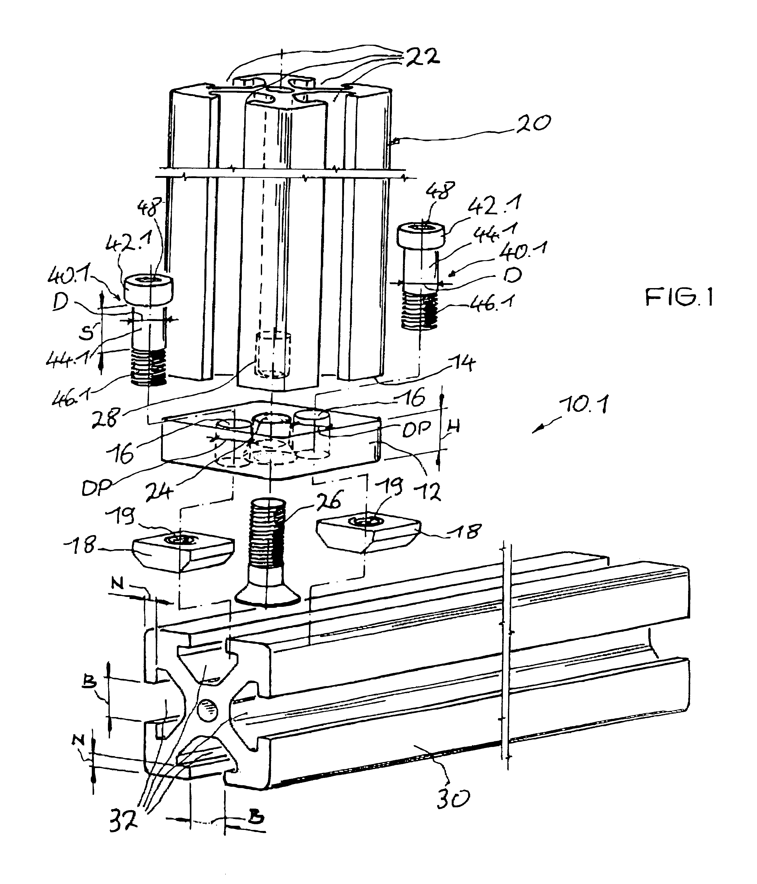
On the basis of the aforementioned prior art, the present invention is based on the object and, respectively, on the technical problem of specifying a connecting device which ensures reliable centering for the connection of two profiled bars with grooves via a plate connector unit, which is easy to mount and can be produced economically.

The connecting device according to the invention is accordingly distinguished by the features of the independent claim 1. Advantageous refinements and developments are the subject of the dependent claims.

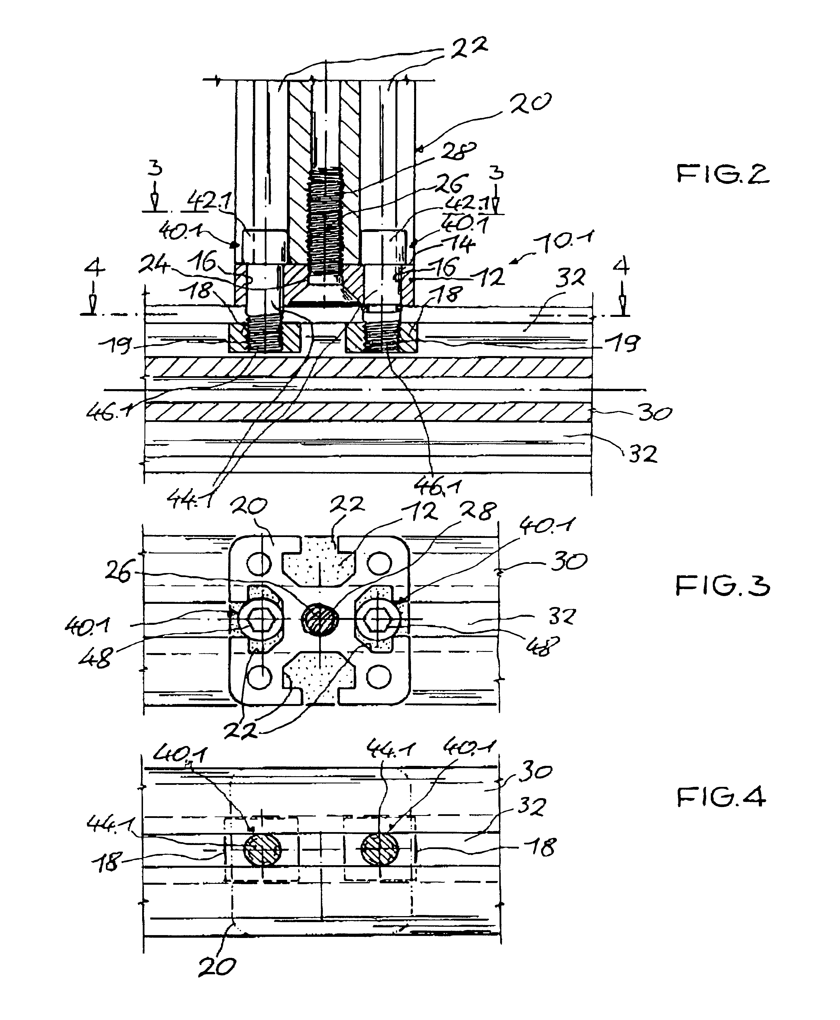
The connecting device according to the invention is accordingly distinguished by the fact that the geometry of the screw head of the screw unit is designed such that it centers the screw unit within the groove in the first profiled bar, and the geometry of the shank of the screw unit is designed such that it engages with a centering effect in the groove in the second profiled bar, or the at least one sliding block that is inserted into the groove in ...


PUM


Abstract

A connecting device for connecting at least two profiled bars that are essentially perpendicular to one another and have grooves, in conjunction with sliding blocks, one plate connector unit is fastened to the end of a first profiled bar and anchored in a groove in the second profiled bar by way of screw units they extend in recesses in the plate connector unit. The geometry of the screw head of the screw unit is configured such that it centers the screw unit within the groove in the first profiled bar and the engages with a centering effect in the groove in the second profiled bar.

Description

TECHNICAL BACKGROUNDThe present invention relates to a connecting device for connecting at least two profiled bars that are essentially perpendicular to one another and have grooves, one plate connector unit being fastened to the end of a first profiled bar and the plate connector unit being anchored in a groove in the second profiled bar by means of screw units extending in recesses in the plate connector unit, in conjunction with sliding blocks.PRIOR ARTA large number of exemplary embodiments for producing a connection between profiled bars with grooves, using a plate connector, are known, but they have the significant drawback that said plate connector is not able to ensure reliable centering of the grooves in the individual profiles connected to one another.DE 195 20 892 A1 discloses a plate connector for connecting two profiles of the type mentioned at the beginning which are essentially perpendicular to each other. In this case, centering means are formed on the plate connecto...

Claims


Application Information

Patent Timeline
IPC IPC(8): F16B7/18E04B1/58
CPCF16B7/187E04B1/5831E04B2001/5881Y10T403/7117Y10T403/4685Y10T403/7094Y10T403/4681Y10T403/4662Y10T403/39F16B2200/20F16B2200/30F16B2200/403
Inventor SCHMALZHOFER, RAINER
Owner FMS FORDER UND MONTAGE SYST SCHMALZHOFER
Why Eureka
Try Eureka