Torsional vibration damper

a torsional vibration and damper technology, applied in the direction of fluid gearings, couplings, resilient suspensions, etc., can solve the problems of very limited bearing support surface of the respective subassembly, and relatively small surface area

Inactive Publication Date: 2004-04-06
MANNESMANN SACHS AG
View PDF12 Cites 12 Cited by
  • Summary
  • Abstract
  • Description
  • Claims
  • Application Information

AI Technical Summary

Benefits of technology

Accordingly, the solution adopted by the present invention is to locate the radial bearing arrangement radially outward from the region utilized in the prior art, so that an appreciably greater surface region is provided for mutual support due to the larger radial distance from the axis of rotation with the same relative rotational angle between the primary side and secondary side. Consequently, the load concentration which occurs in the prior art is reduced and excessive wear in the region of the subassemblies used for mutual radial bearing support of the primary side and secondary side may be prevented.
A radial bearing arrangement which operates with particularly low wear may be achieved in that the radial bearing arrangement includes a plurality of bearing roller elements rotatably arranged at one side of the primary side and secondary side. The other side of the primary side and secondary side is movable relative to the one side and a plural bearing roller elements via a bearing surface.

Problems solved by technology

Due to the small radial distance from the axis of rotation, the bearing surface of the respective subassembly available for bearing support is very limited.
However, this results in a relatively small surface region of the surfaces or components used for mutual radial bearing support being passed over.

Method used


Image

  • Torsional vibration damper
  • Torsional vibration damper
  • Torsional vibration damper

Examples


Embodiment Construction

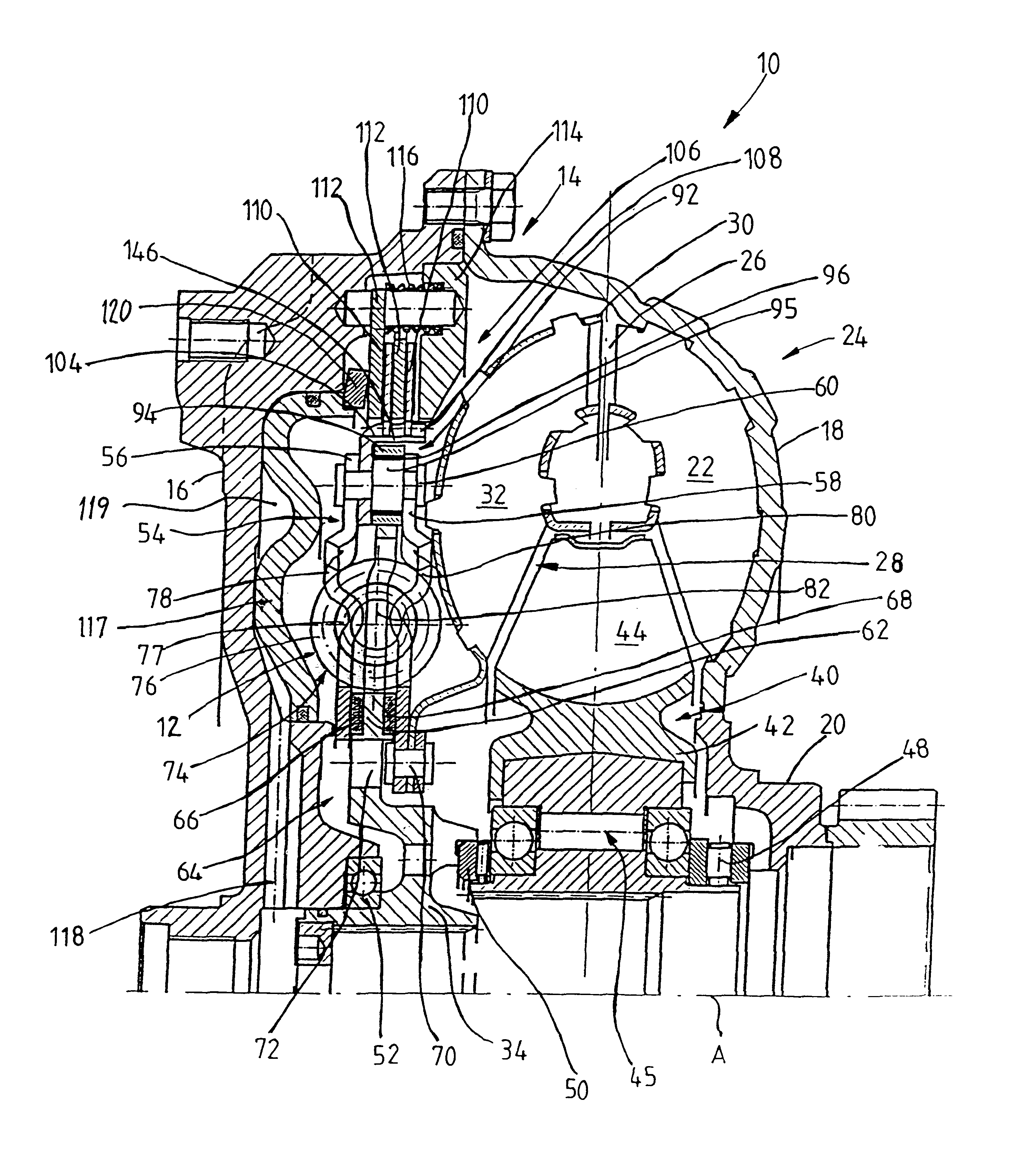
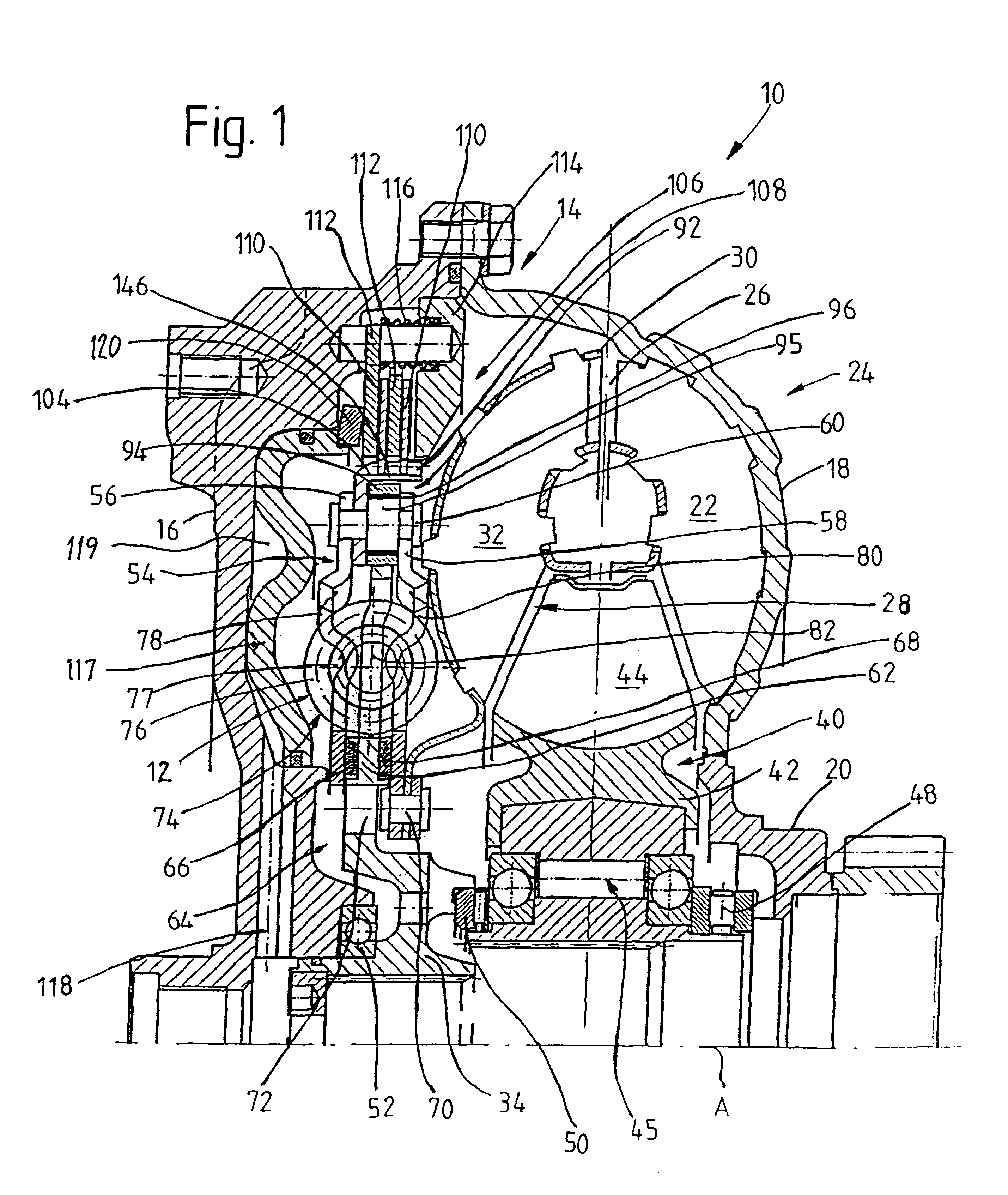
FIG. 1 is a sectional view of a hydrodynamic torque converter 10 including a torsional vibration damper 12 according to the present invention. The torque converter 10 comprises a housing 14 which includes a housing cover 16 and an impeller wheel shell 18. A radial outer side of the impeller wheel shell 18 is connected with the housing cover 16. A radial inner side of the impeller wheel shell 18 is connected with an impeller wheel hub 20. Further, a plurality of impeller wheel blades 22 are connected at an inner side of the impeller wheel shell 18. The impeller wheel hub 20, the impeller wheel shell 18, and the impeller wheel blades 22 together form an impeller wheel 24. A turbine wheel 28 is arranged in an interior 26 of the torque converter 10. The turbine wheel 28 has a turbine wheel shell 30 with a plurality of turbine wheel blades 32 on a side of the turbine wheel 28 facing the impeller wheel 24. The turbine wheel 28 further comprises a turbine wheel hub 34 which is connectable ...


PUM


Abstract

A torsional vibration damper for a hydrodynamic clutch device particularly for coupling a turbine wheel hub with a turbine wheel shell and / or for coupling a lockup clutch arrangement with a turbine wheel, includes a primary side and a secondary side which is rotatable about an axis of rotation with respect to the primary side against the action of a damper element arrangement. A radial bearing arrangement is arranged for radially supporting the primary side and secondary side with respect to one another. For this purpose, the radial bearing arrangement is arranged radially outside of the damper element arrangement.

Description

1. Field of the InventionThe present invention relates to a torsional vibration damper for coupling a turbine wheel hub with a turbine wheel shell in a hydrodynamic clutch device and / or for coupling a lockup clutch arrangement with a turbine wheel, the torsional vibration damper including a primary side and a secondary side which is rotatable about an axis of rotation with respect to the primary side against the action of a damper element arrangement, and a radial bearing arrangement for supporting the primary side and secondary side with respect to one another in radial direction.2. Description of the Related ArtGerman reference DE 197 24 973 C1 discloses a torsional vibration damper in which the primary side and the secondary side of the torsional vibration damper comprise various subassemblies of a turbine wheel hub. That is, a first subassembly part of the turbine wheel hub, which is associated with the turbine wheel shell with respect to rotary operation since it is fixedly con...

Claims


Application Information

Patent Timeline
Patent Type & Authority Patents(United States)
IPC IPC(8): F16H45/00F16H45/02
CPCF16H45/02F16H2041/246F16H2045/021F16H2045/0247F16H2045/0284
Inventor SCHMID, HERBERT
Owner MANNESMANN SACHS AG
Why Eureka
Try Eureka