Plasma processing equipment

a technology of processing equipment and plasma, which is applied in the direction of plasma technique, chemical vapor deposition coating, coating, etc., can solve the problems of difficult to generate plasma stably in a low pressure (20 mtorr) and various thicknesses of dielectric bodies

Inactive Publication Date: 2011-04-26
TOKYO ELECTRON LTD
View PDF15 Cites 9 Cited by
  • Summary
  • Abstract
  • Description
  • Claims
  • Application Information

AI Technical Summary

Benefits of technology

[0012]It is an object of the present invention to provide a plasma processing equipment which can form an optimal resonant region in a top plate according to a plasma condition, and generate plasma stably in a chamber over a range from a low pressure to high pressure.
[0014]According to the present invention, since a thickness of the top plate in a diameter direction is sequentially varied by the tapered part of the convex portion or concave portion formed in the top plate, an optimal resonant region can be surely formed under any plasma condition. Therefore, only one kind top plate has the same effect as a top plate having various thicknesses, so that absorption efficiency to plasma can be considerably improved and the plasma can be generated stably over a range from a high pressure to a low pressure.

Problems solved by technology

Therefore, when plasma is to be generated in an optimal state constantly, there is a problem in which it is necessary to prepare a dielectric body having various kinds of thicknesses according to plasma conditions.
In addition, since absorption efficiency of the microwave to plasma is low in a low pressure, it is difficult to generate plasma stably in a low pressure (20 mTorr).

Method used


Image

  • Plasma processing equipment
  • Plasma processing equipment
  • Plasma processing equipment

Examples


Embodiment Construction

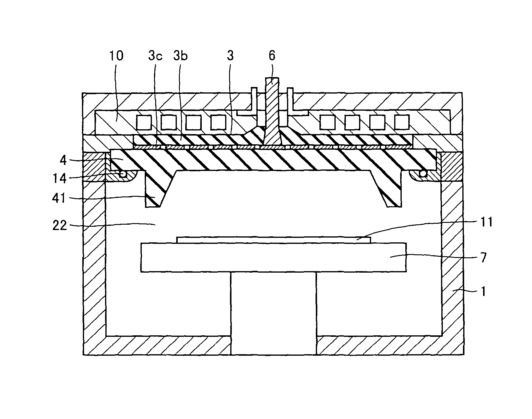
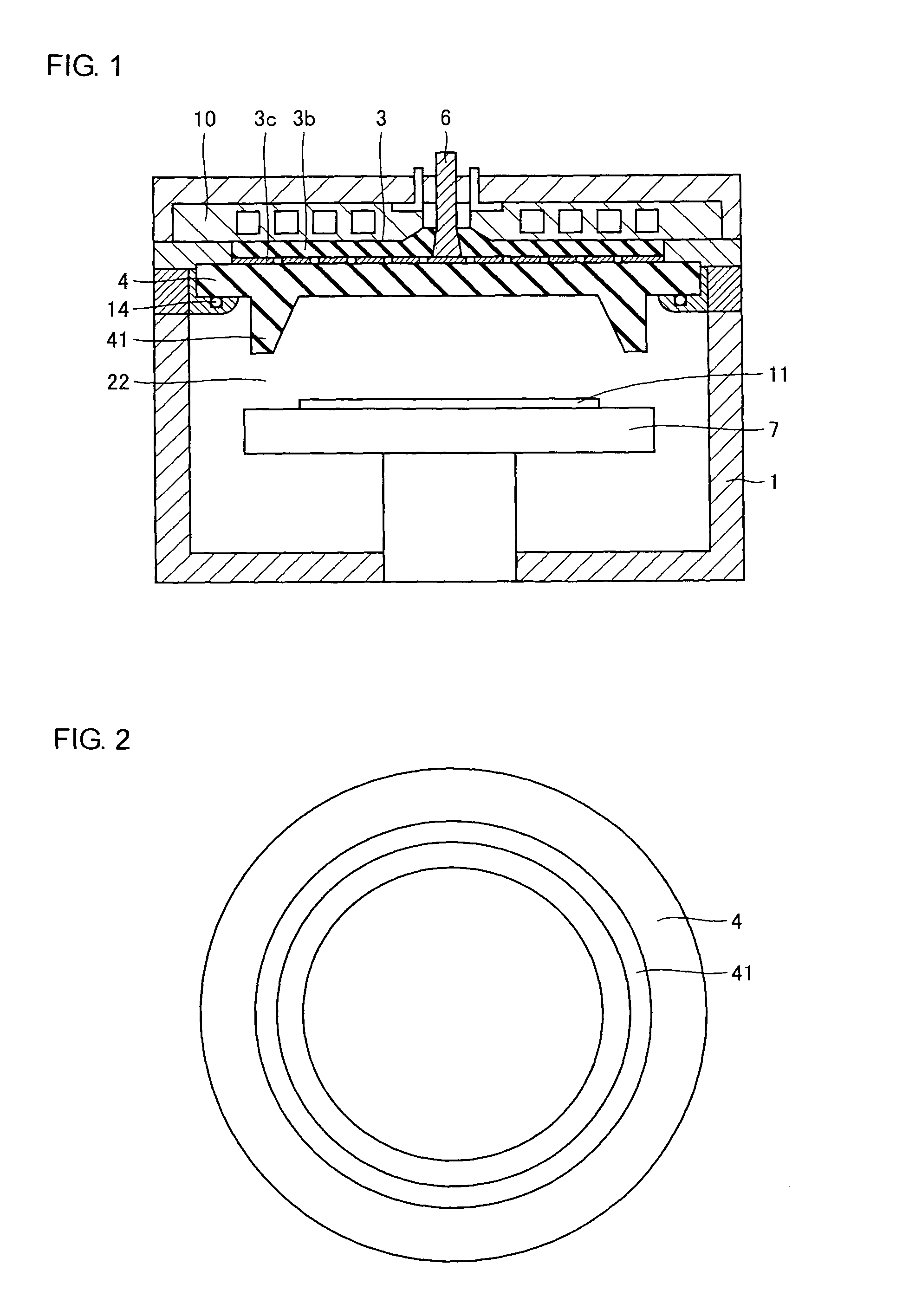
[0050]FIG. 1 is a sectional view showing a plasma processing equipment according to one embodiment of the present invention, and FIG. 2 is a view showing a dielectric plate as viewed from beneath in FIG. 1.

[0051]Similar to FIG. 18, the plasma processing equipment comprises a chamber 1 in which a substrate 11 is housed and processed, and an antenna 3 for emitting a microwave into the chamber 1.

[0052]The microwave generated by a high-frequency power supply (not shown) is transmitted to the antenna 3 through a waveguide 6. A top plate 4 which seals an opening of the chamber 1 and constitutes a part of a wall of the chamber 1 is provided at an upper part of the chamber 1, and a sealing member 14 such as an O ring is provided between the top plate 4 and the wall of the chamber 1. The antenna 3 is provided on the top plate 4. A cooling plate 10 in which a cooling medium flows is provided on the antenna 3.

[0053]A table 7 on which the housed substrate 11 is held is provided in the chamber 1...


PUM

PropertyMeasurementUnit
frequencyaaaaaaaaaa
pressureaaaaaaaaaa
thicknessaaaaaaaaaa

Abstract

Resonance can be surely provided under any plasma condition in such a manner that an antenna (3) is arranged in an opening of an upper part of a chamber (1) to produce an electromagnetic field generated by a microwave, a top plate (4) for sealing the opening of the chamber (1) is provided under the antenna (3), a ring-shaped ridge (41) is provided on a lower surface of the top plate (4) such that a thickness thereof in a diameter direction is tapered so as to be varied sequentially. Thus, only one kind of top plate has the same effect as a top plate having various thicknesses, so that absorption efficiency to the plasma can be considerably improved and the plasma can be generated stably over a range from a high pressure to a low pressure.

Description

TECHNICAL FIELD[0001]The present invention relates to a plasma processing equipment and more particularly, to a plasma processing equipment which generates plasma in a chamber by emitting a microwave supplied to an antenna through a top plate formed of a dielectric material to seal an opening of the chamber.BACKGROUND ART[0002]Recently, as a semiconductor device is highly densified and miniaturized, a plasma processing equipment is used to perform processing such as depositing, etching and ashing in a manufacturing process of the semiconductor device. In particular, according to a microwave plasma processing equipment which can generate plasma with a microwave, plasma can be stably generated even under a (high-vacuum) condition in which a pressure is relatively as low as about 0.1 to 10 Pa. Therefore, a microwave plasma processing equipment using a microwave having a frequency of 2.45 GHz, for example attracts a lot of attention.[0003]FIG. 18 is a sectional view showing an example o...

Claims


Application Information

Patent Timeline
Patent Type & Authority Patents(United States)
IPC IPC(8): C23C16/00H01L21/306C23F1/00H05H1/46C23C16/511H01J37/32H01L21/304
CPCH01J37/32192H01J37/32458H01J37/32238
Inventor NOZAWA, TOSHIHISAISHIBASHI, KIYOTAKA
Owner TOKYO ELECTRON LTD
Why Eureka
Try Eureka