Production of Nanoparticles

a technology of nanoparticles and nanoparticles, which is applied in the direction of electrodes, diaphragms, ion implantation coatings, etc., can solve the problems of difficult and difficult production of such particles, and achieve the effect of increasing the size and the time in the region

Inactive Publication Date: 2012-06-21
MANTIS DEPOSITION
View PDF3 Cites 9 Cited by
  • Summary
  • Abstract
  • Description
  • Claims
  • Application Information

AI Technical Summary

Benefits of technology

[0006]This works by allowing the charged nanoparticles to encounter a like electrical potential, i.e. an electrical potential that is the same sign as that of the charge on the nanoparticles. As they enter this region, they will slow and, therefore spend a greater time in that region. One or more PVD sources directed at the region will then be able to create a vapour of the intended shell material which will deposit on the slower-moving nanoparticles, increasing their size and creating the desired core / shell structure.

Problems solved by technology

The evident problem lies in the production of such particles.
Given that a nanoparticle might consist of a mere 50,000 atoms, this is not a straightforward task.

Method used


Image

  • Production of Nanoparticles
  • Production of Nanoparticles
  • Production of Nanoparticles

Examples


Embodiment Construction

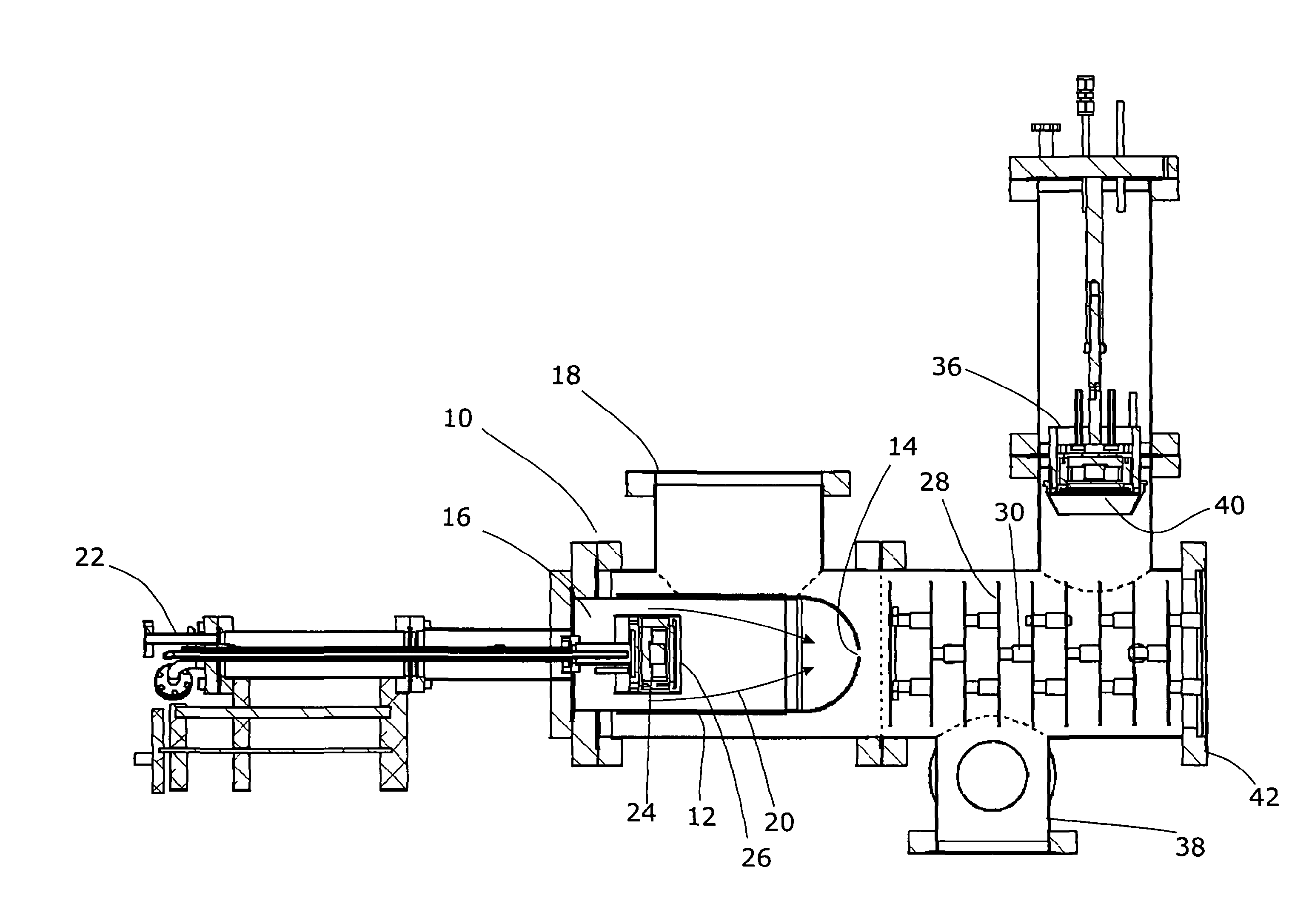
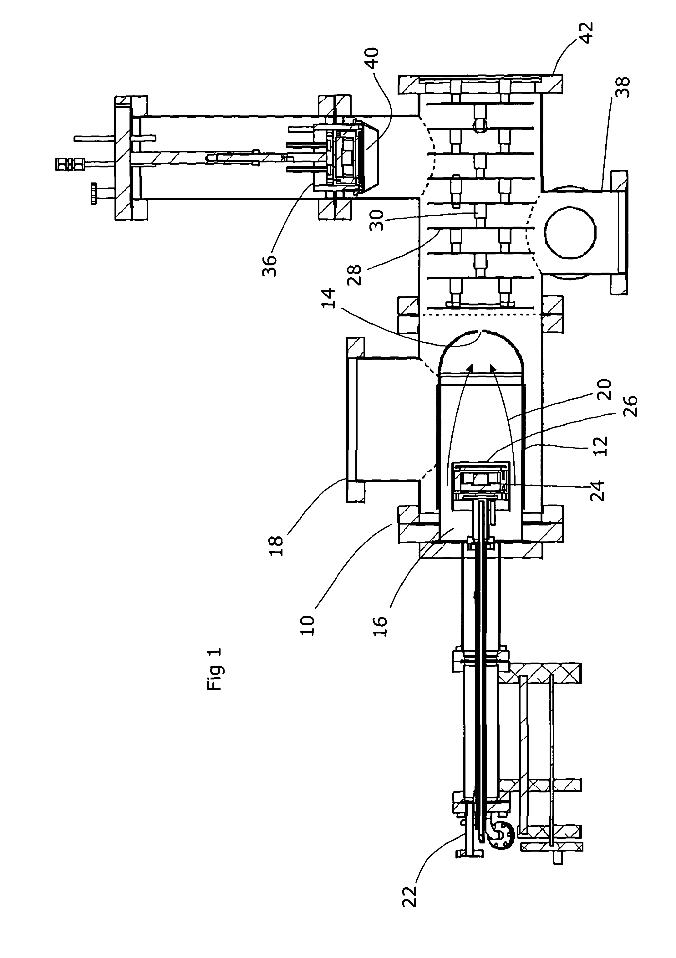
[0014]Referring to FIG. 1, an apparatus for the production of composite nanoparticles is disclosed. This consists of, on the left hand side as illustrated in FIG. 1, an apparatus 10 for producing nanoparticles. These nanoparticles will eventually form the core of the resulting composites of nanoparticles. An enclosure 12 has an outlet 14 at its right-most end and contains a gas 16 at a low pressure. This is enclosed within a vacuum chamber 18, and accordingly the low pressure gas 16 is at an elevated pressure relative to the surrounding space. As a result, the low pressure gas 16 will escape via the outlet 14, forming a flow of gas as illustrated by arrows 20. A gas inlet 22 is accordingly provided at the left-most end of the enclosure 12, in order to maintain and replenish the supply of low pressure gas 16.

[0015]A sputter deposition apparatus 24 is provided within the enclosure 12, and is generally conventional in nature. A sputter target 26 is provided, of the material intended fo...


PUM

PropertyMeasurementUnit
sizeaaaaaaaaaa
electrically resistiveaaaaaaaaaa
voltageaaaaaaaaaa

Abstract

Composite nanoparticles can be produced by a processing apparatus comprising a source of charged, moving nanoparticles or a first material and a first size, apparatus for imposing a like potential in a region lying in the path of the nanoparticles, and a physical vapour deposition source of a second material directed toward the region, thereby to produce nanoparticles of a second and greater size being a composite of the first and second materials. The apparatus for imposing a like potential can comprise one or more conductive rings surrounding the path of the nanoparticles, each at a successively lower potential. The physical vapour deposition source can be one or more of a sputter target, or an evaporative source, or another PVD source. There can be a plurality of physical vapour deposition sources, thereby allowing a larger region in which the shell is deposited. All of the physical vapour deposition sources can deposit the same material, for a uniform shell. Alternatively, different sources could allow for multiple shells or alloy shells.

Description

FIELD OF THE INVENTION[0001]The present invention relates to the production of nanoparticles.BACKGROUND ART[0002]Nanoparticles can be produced by a range of methods, including vacuum deposition processes. Normal deposition processes call for the material to be evaporated into a vacuum chamber and then deposited onto a substrate. To produce nanoparticles, the evaporated material can be allowed to linger in the gaseous phase to permit nucleation of nanoparticles.SUMMARY OF THE INVENTION[0003]The present invention addresses the problem of creating composite nanoparticles. There is a demand for nanoparticles which comprise an inner core surrounded by an outer shell or coating, for a range of reasons. In some cases, this is because it is the surface of a nanoparticle that is effective, so where the desired material is particularly expensive (such as Platinum) it can be more cost-effective to use the expensive material only on the outer parts of the nanoparticle where it will have some ef...

Claims


Application Information

Patent Timeline
Patent Type & Authority Applications(United States)
IPC IPC(8): C23C14/34
CPCC23C14/223
Inventor ALLERS, LARSKEAN, ALISTAIRWYNNE-POWELL, THOMAS MATTHEW
Owner MANTIS DEPOSITION
Why Eureka
Try Eureka