Centrifuge with a fluid line guide element having a curved bearing surface

a technology of fluid line guide element and centrifuge, which is applied in the direction of centrifuge, blood transfusion, etc., can solve the problems of affecting the operation of centrifuge, so as to achieve high rotational speed, low mechanical stress, and easy manufacturing. easy and inexpensive

Inactive Publication Date: 2004-04-06
FRESENIUS HEMOCARE BETEILIGUNGS
View PDF24 Cites 7 Cited by
  • Summary
  • Abstract
  • Description
  • Claims
  • Application Information

AI Technical Summary

Benefits of technology

The object of the present invention is to create a centrifuge that can be manufactured especially easily and inexpensively, whose line for supplying and/or removing the fluid is adequately supported on the

Problems solved by technology

Because of the relative movement of the centrifuge chamber and the stationary tie-in point of the line, however, guidance of the line has proven to be problematical.
Such continuous-flow centrifuges allow a high rotational speed, but the rotational couplings may lead to leakage and damage to components contained in the fluid.
In the case of continuous-flow centrifuges that do not use face seals, the line is exposed to relatively great mechanical stresses that increase greatly with an increase in rotat

Method used


Image

  • Centrifuge with a fluid line guide element having a curved bearing surface
  • Centrifuge with a fluid line guide element having a curved bearing surface
  • Centrifuge with a fluid line guide element having a curved bearing surface

Examples


Embodiment Construction

A representative embodiment of the present invention is described in greater detail below with reference to the drawings.

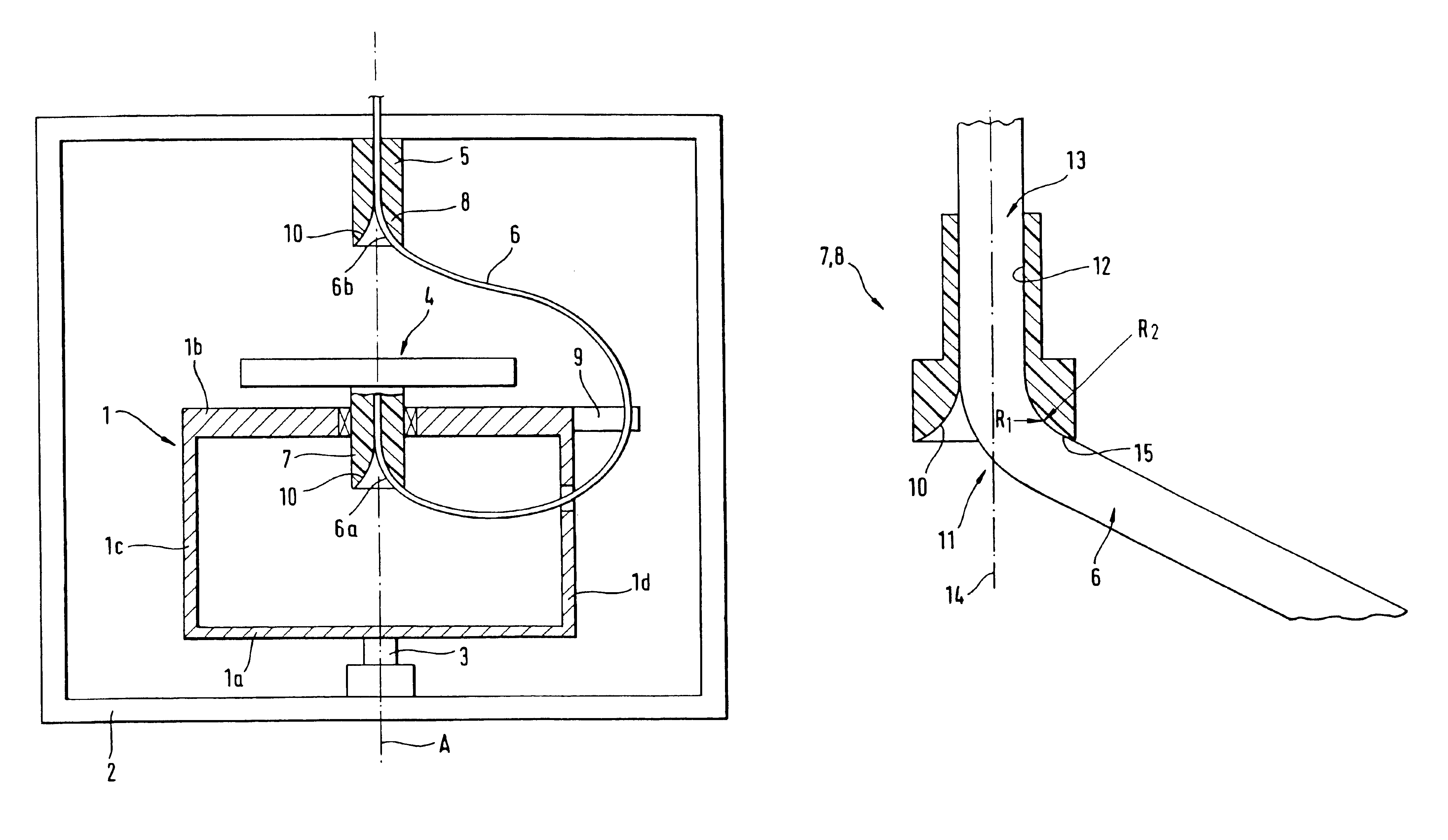
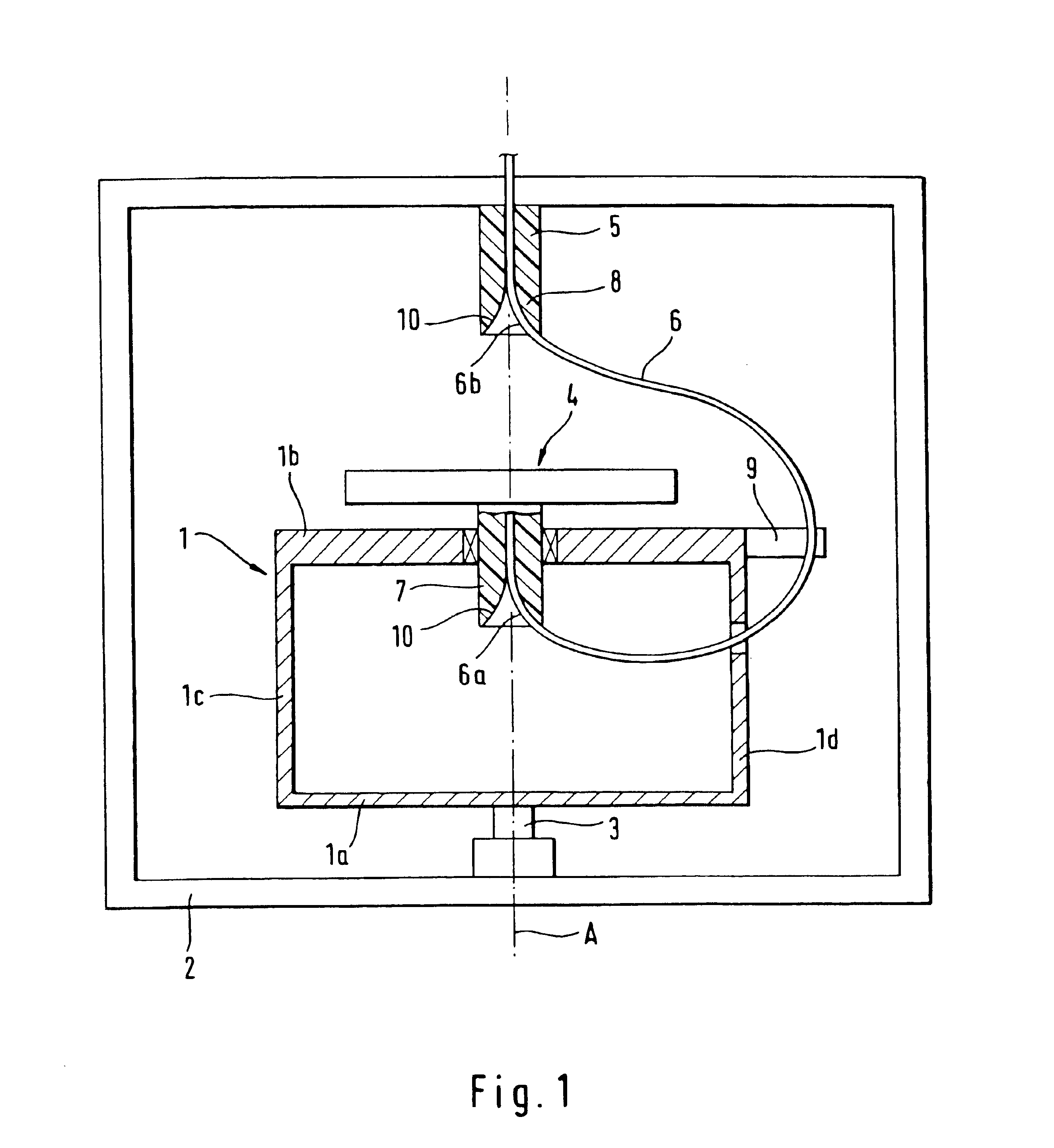
FIG. 1 shows a schematic diagram of a continuous-flow centrifuge that does not use face seals for centrifuging a biological fluid, in particular blood, which corresponds in design and function to the centrifuge described in German Patent 32 42 541 A1. The continuous-flow centrifuge has a rotating frame 1 with a lower supporting plate 1a and an upper supporting plate 1b plus two side parts 1c, 1d. Rotating frame 1 is rotatably mounted on a stationary frame 2 to rotate about a vertical axis 3, and it is driven by a drive unit (not shown in FIG. 1) at a rotational speed n.sub.1. A separation unit 4 in the form of a cylindrical chamber is mounted on the upper supporting plate 1b of the rotating frame 1 so it can rotate about the axis of rotation of rotating frame 1. Separation unit 4 is driven by a drive unit (not shown) in the same direction of rotation as the rotati...


PUM


Abstract

A centrifuge having a rotating frame, which is rotatably mounted on a stationary frame, and a separation unit mounted on the rotating frame, rotating about a central axis of rotation in the same direction of rotation as the rotating frame but at twice the rotational speed. A line for supplying and/or removing a fluid is connected to the separation unit and is guided in a loop about the separation unit to a stationary tie-in point. To support the line, at least one guide element having a bearing surface for the line is provided. The bearing surface of the guide element is formed by a rotating planar curve, where the radius of the respective circle of curvature contacts the curve at a point and increases with increasing distance between the contact point and the central axis of rotation. With this contour, abrasion over the entire contact surface is largely uniform, which thereby lengthens the lifetime.

Description

FIELD OF THE INVENTIONThe present invention relates to a centrifuge, in particular a continuous-flow centrifuge without face seals for centrifuging biological fluids.BACKGROUND OF THE INVENTIONCentrifuges are known in which the biological fluid is centrifuged in continuous flow. The fluid is supplied to a rotating centrifuge chamber and removed from the chamber through a line. Because of the relative movement of the centrifuge chamber and the stationary tie-in point of the line, however, guidance of the line has proven to be problematical. To prevent twisting of the line, rotating seals are used at the tie-in points of traditional continuous-flow centrifuges. Such continuous-flow centrifuges allow a high rotational speed, but the rotational couplings may lead to leakage and damage to components contained in the fluid.A blood centrifuge without face seals is disclosed in German Patent 32 42 541 A1. With this centrifuge, which does not use face seals, the line passes from a stationary...

Claims


Application Information

Patent Timeline
IPC IPC(8): B04B5/00B04B5/04A61M1/02
CPCB04B5/0442B04B2005/0492
Inventor WITTHAUS, FRIEDRICHWEBER, WOLFRAM
Owner FRESENIUS HEMOCARE BETEILIGUNGS
Why Eureka
Try Eureka