Vibration testing device and vibration response evaluating method

a vibration testing and vibration response technology, applied in the direction of vibration measurement in solids, fluid pressure measurement by mechanical elements, fluid tightness measurement, etc., can solve the problems of waste of the whole cost of the test, failure of the test, and inability to consider conventional techniques

Inactive Publication Date: 2004-04-06
HITACHI IND PROD LTD
View PDF10 Cites 35 Cited by
  • Summary
  • Abstract
  • Description
  • Claims
  • Application Information

AI Technical Summary

Problems solved by technology

It is difficult from the economical viewpoint that one experimental facility holds an experimental device suitable for the vibration test for such a huge structure.
However, such a computer is often put in a different place from the vibration experimental facility.
Thus, these conventional techniques do not consider the above theme.
Furthermore, the techniques disclosed in JP-A-9-79939 and JP-A-10-206304 mentioned above do not take into consideration a conception of actively varying command signals from the computer in accordance with responses such as the deformation and load of the test piece generated with vibration given by the actuator.
In the case of a vibration test using plural actuators, however, if some trouble has occurred in one actuator and as a result, the reaction of the corresponding test piece cannot be obtained, the test will end in failure though the other actuators are out of any trouble.
In such a case, the whole expense of the test can be wasteful.

Method used


Image

  • Vibration testing device and vibration response evaluating method
  • Vibration testing device and vibration response evaluating method
  • Vibration testing device and vibration response evaluating method

Examples


Embodiment Construction

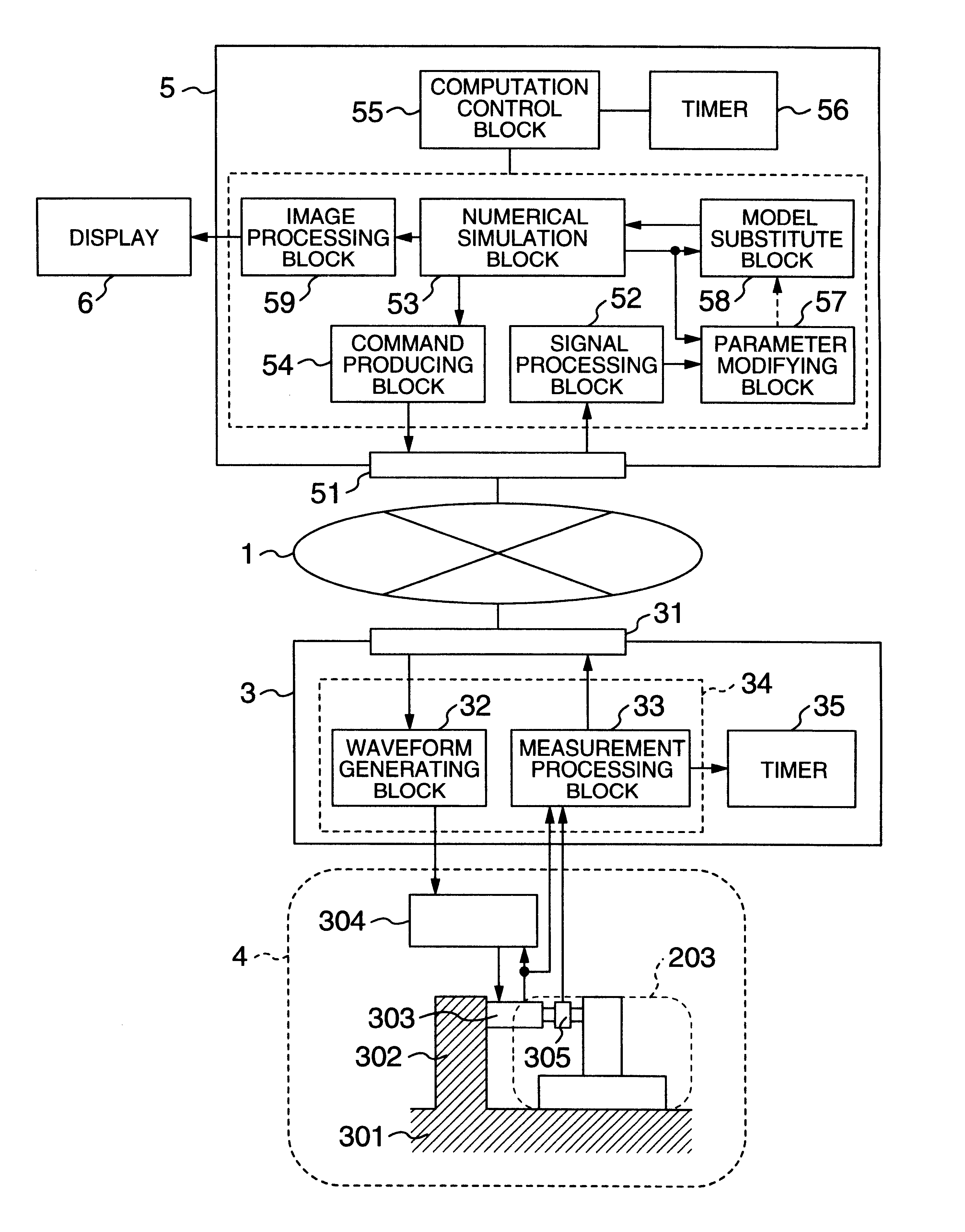
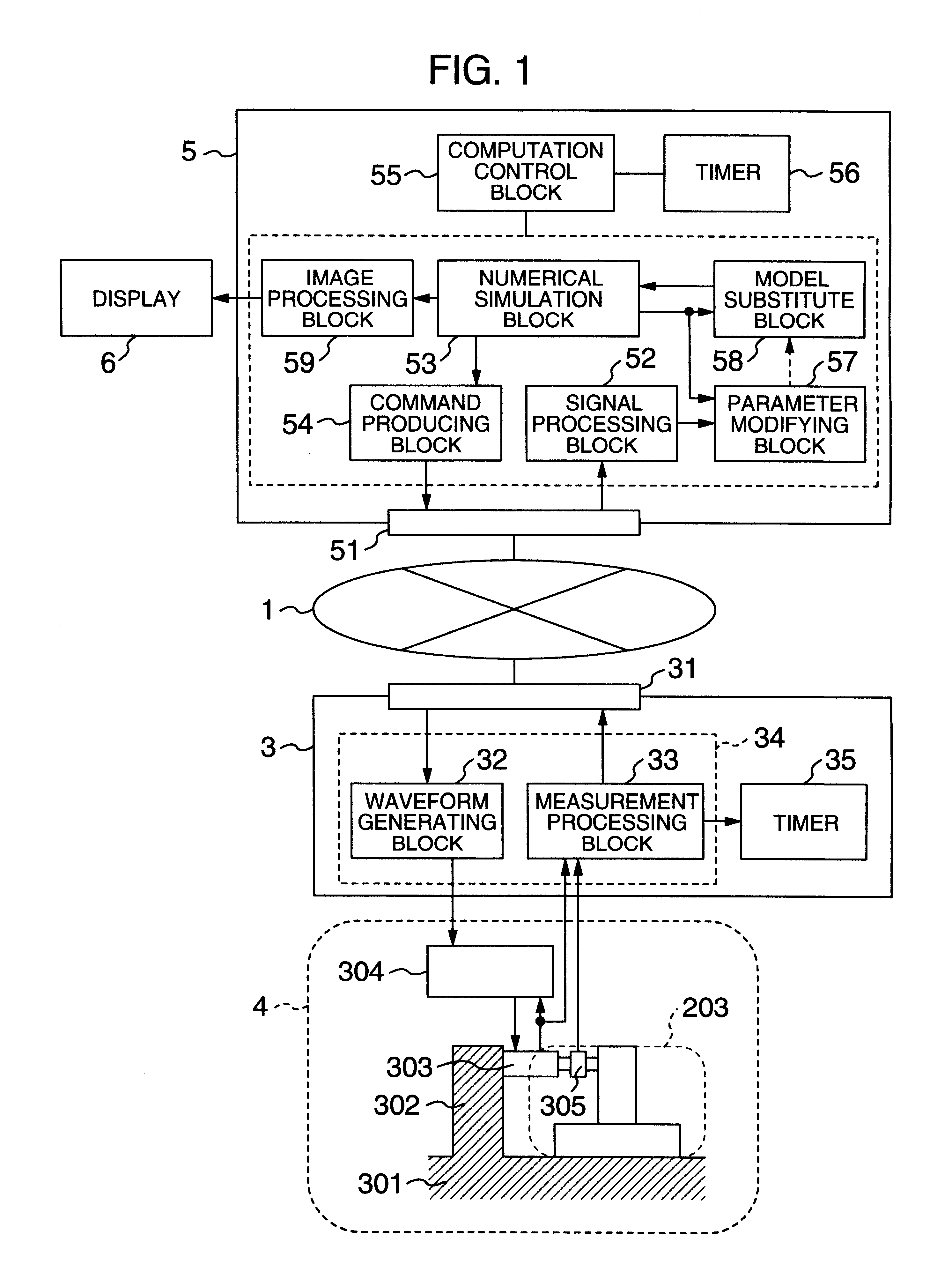
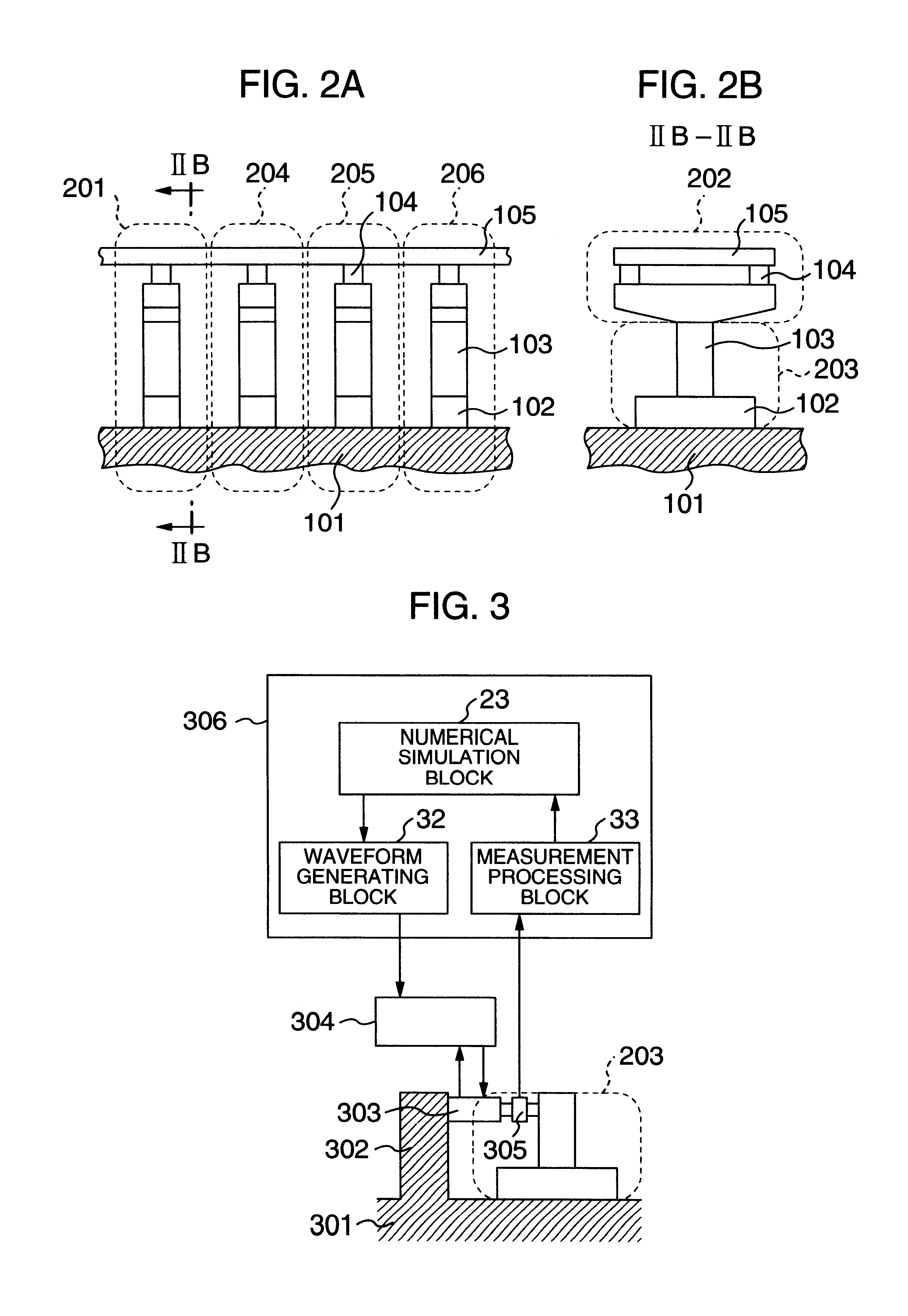
In the following, an embodiment of the present invention will be described with reference to the drawings. Here, an embodiment of the present invention will be described with using the vibration test for a bridge beam shown in FIG. 2 as an example. First, considerations will be given to a vibration testing device shown in FIG. 3. In the vibration test for the bridge beam as shown in FIG. 2, the same number of actuators as that of the concerned support structures may be connected to a computer 306. However, the configuration of the actuator and the dynamic characteristics thereof and the characteristics of a sensor and the installation condition thereof are different depending on the respective facility for the actuator and the test piece. Therefore, if all of the waveform generating blocks 32 and measurement processing blocks 33 for the actuator are mounted to the computer 306, processes such as data inputting become complicated. As a result, the versatility as an experimental appar...


PUM

PropertyMeasurementUnit
structure numerical modelaaaaaaaaaa
secondary structure modelaaaaaaaaaa
strengthaaaaaaaaaa

Abstract

A vibration testing device includes a computer system having: a measurement processing block for inputting an output of the monitoring sensor and processing the output; a model substituting block for modeling characteristics of the test piece, calculating a response quantity corresponding to a drive condition of an actuator, and inputting the calculation result to a numerical simulation block and the parameter changing block; the parameter changing block for comparing the calculation result of the model substituting block with the processing result of the measurement processing block, and changing the parameter; the numerical simulation block for calculating a vibration response in accordance with a previously input structure numerical model; and a waveform generating block for calculating a time function of a deformation to be applied to the test piece, and outputting the time block to the actuator controlling device.

Description

1. Field of the InventionThe present invention relates to an actuator system and a vibration testing method used for evaluating characteristics of a structure which influences an earthquake response or for proving the strength and reliability of the structure by applying a deformation and a load to the structure. More particularly, it relates to a vibration testing device and a method for evaluating a vibration response suitable for a huge structure.2. Description of the Related ArtA structure is required to be designed so as to have sufficient strength to a load which may be applied to the structure during its use. For example, for building and civil engineering structures, it is important to design them so as to have the sufficient strength to the severest earthquake that may take place during their use. Therefore, a vibration test is carried out to examine a vibration response of the structure itself to the earthquake or to test characteristics of members which influence the eart...

Claims


Application Information

Patent Timeline
Patent Type & Authority Patents(United States)
IPC IPC(8): G01M7/00G01M7/02
CPCG01M7/00
Inventor HORIUCHI, TOSHIHIKOKONNO, TAKAO
Owner HITACHI IND PROD LTD
Why Eureka
Try Eureka