Shielded strip line device and method of manufacture thereof

a technology of shielding strip and strip line, which is applied in the direction of waveguide devices, electrolytic capacitors, waveguide types, etc., can solve the problems of lowering signal quality, increasing the impedance of capacitors, and placing more difficult demands on noise filter bypass devices and power decoupling devices

Inactive Publication Date: 2004-04-13
NEC CORP
View PDF8 Cites 15 Cited by
  • Summary
  • Abstract
  • Description
  • Claims
  • Application Information

AI Technical Summary

Benefits of technology

An object of this invention is to provide a shielded strip line device, which is low in impedance, especially in high-frequency regions of 100 MHz or more, and is favorably adapted to high speed and high frequencies, mainly for use as a bypass device for a noise filter or as a decoupling device.

Problems solved by technology

However, this causes an increase in the high frequency current that flows through the circuit, in particular the power supply circuit, causing significant increase in electromagnetic radiation and lowering of signal quality and thus placing more difficult demands on the performance of noise filter bypass devices and power decoupling devices.
However, even these capacitors increase dramatically in impedance and cannot meet recent demands as filter bypass devices and power decoupling devices in high frequency ranges in the excess of 10 MHz.
However, this prior art has the following problem.
As a result, these capacitors cannot meet recent demands as filter bypass devices or power decoupling devices.
Also, though surface-mounted filters for the purpose of noise elimination have also been developed, these cannot realize an infinitely low impedance value and are thus limited in use as substitutes for capacitors.
It is thus difficult to realize low impedance especially in high-frequency regions of 100 MHz or more with such filters.

Method used


Image

  • Shielded strip line device and method of manufacture thereof
  • Shielded strip line device and method of manufacture thereof
  • Shielded strip line device and method of manufacture thereof

Examples


first embodiment

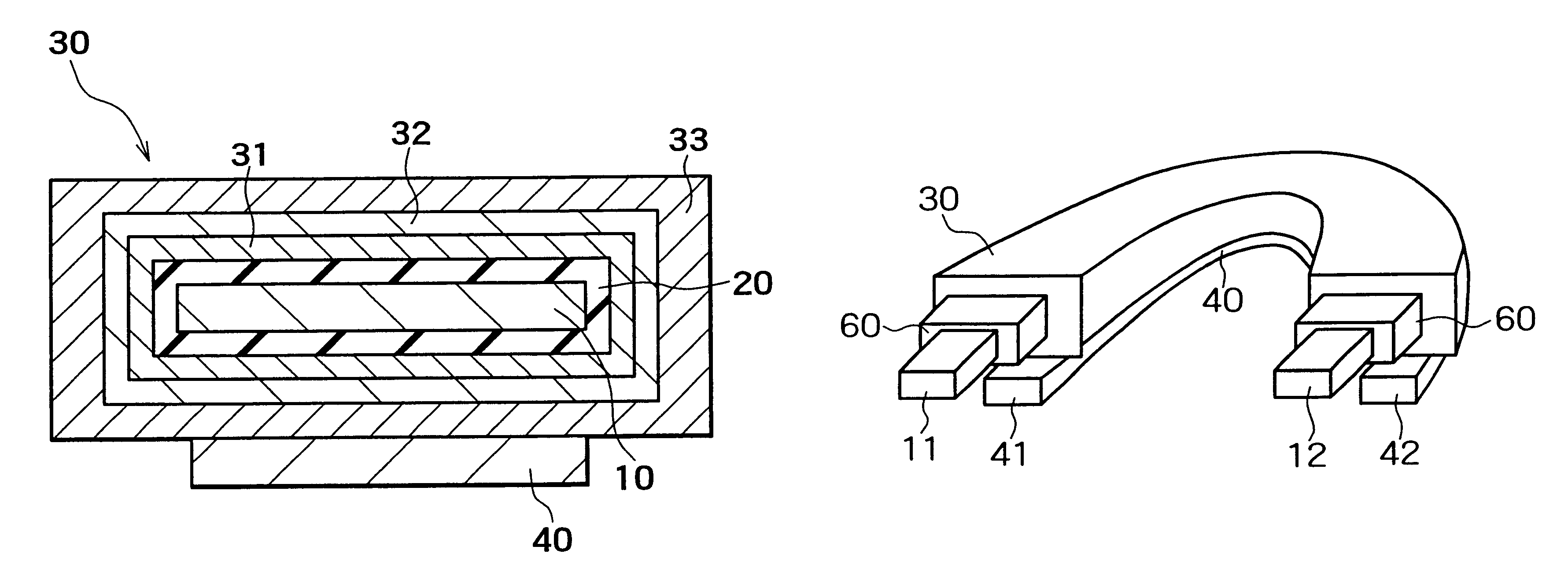
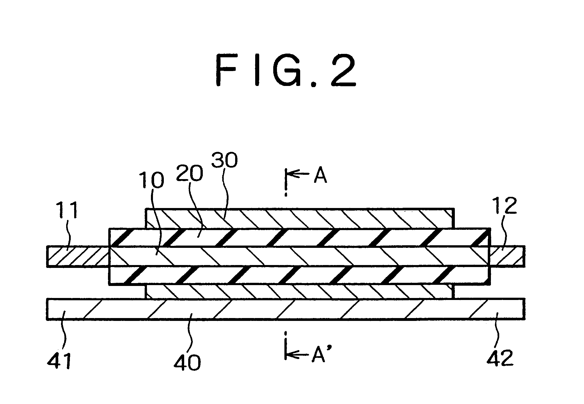
Embodiments of the present invention shall now be described with reference to the attached drawings. First, the present invention shall be described. FIG. 2 is a sectional view, showing a shielded strip line device of the embodiment, and FIG. 3 is a sectional view, showing the section along line A-A' of FIG. 2.

As shown in FIGS. 2 and 3, with the shielded strip line device of the present embodiment, a metal plate 10, which comprises a valve metal and is substantially of a planar shape, is provided. Valve metal plate 10 is formed, for example, of aluminum. Valve metal plate 10 is rectangular in shape and, for example, 110 .mu.m in thickness, 20 mm in length, and 10 mm in width. The surface of valve metal plate 10, that is, the top face, rear face, and end faces are increased by approximately 200 times in surface area by electrolytic etching in an electrolytic solution.

A dielectric oxide film 20 is formed on the surface of this valve metal plate 10. Dielectric oxide film 20 is formed b...

second embodiment

this invention shall now be described. In comparison to the arrangement of the shielded strip line device of the first embodiment described above, the arrangement of the shielded strip line device of the present embodiment differs in that a conductive polymer layer 31 is formed of polypyrrole. Besides this, the shielded strip line device of the present embodiment is the same in arrangement as the shielded strip line device of the first embodiment.

A method of manufacturing the shielded strip line device of the present embodiment shall now be described. First, by the same method as that of the first embodiment, a dielectric oxide film 20 and masks are formed on the surface of a valve metal plate 10. A methanol solution containing 10% by mass of ferric dodecylbenzenesulfonate is then prepared in a glass container. The abovementioned valve metal plate 10, with which dielectric oxide film 20 has been formed on the surface, is immersed in and then taken out from this solution. The valve m...

third embodiment

this invention shall now be described. In comparison to the arrangement of the shielded strip line device of the first embodiment described above, the arrangement of the shielded strip line device of the present embodiment differs in that a conductive polymer layer 31 is formed of polyhexylthiophene. Besides this, the shielded strip line device of the present embodiment is the same in arrangement as the shielded strip line device of the first embodiment.

A method of manufacturing the shielded strip line device of the present embodiment shall now be described. First, by the same method as that of the first embodiment, a dielectric oxide film 20 and masks are formed on the surface of a valve metal plate 10. A xylene solution with a polyhexylthiophene concentration of 5% by mass is then prepared in a glass container, this solution is dripped onto the non-masked regions of the abovementioned valve metal plate 10, with which dielectric oxide film 20 and masks have been formed on the surfa...


PUM

PropertyMeasurementUnit
frequencyaaaaaaaaaa
frequencyaaaaaaaaaa
frequencyaaaaaaaaaa

Abstract

A dielectric oxide film is formed on the surface of a valve metal plate formed of aluminum and a conductive polymer layer is provided so as to cover the valve metal plate and the dielectric oxide film. The conductive polymer layer is formed of polyaniline having para-toluenesulfonic acid as a dopant. A conductive carbon paste layer and a silver paste layer are provided at the outer side of the conductive polymer layer and a metal plate, comprising a copper foil, is overlapped onto the silver paste layer. Anode lead terminals are connected to the ends of the valve metal plate and the respective end parts of the metal plate are arranged as cathode lead terminals. A shield strip line device, which is low in impedance, especially in high-frequency ranges of 100 MHz or more, and is favorably adapted to high speed and high frequencies, mainly for use as a bypass device for a noise filter or as a decoupling device, is thus obtained.

Description

1. Technical Field of the InventionThis invention relates to a shielded strip line device to be mounted on a circuit board or an electronic substrate and a method of manufacture thereof, and particularly relates to a shielded strip line device, which is favorably adapted to high speeds and high frequencies, mainly for use as a noise filter bypass device or power decoupling device, and a method of manufacturing such a shielded strip line device.2. Description of the Related ArtWith the progress of scientific technologies, the making of electronic equipment more compact and higher in performance is being demanded. This is achieved, for example in switching power supplies and digital signal processing circuit parts, by making the clock frequency higher. However, this causes an increase in the high frequency current that flows through the circuit, in particular the power supply circuit, causing significant increase in electromagnetic radiation and lowering of signal quality and thus pla...

Claims


Application Information

Patent Timeline
Patent Type & Authority Patents(United States)
IPC IPC(8): H03H1/00H01G9/012H01G9/042H01G9/10H01G9/15H01P3/08H01P11/00
CPCH01G9/012H01G9/042H01G9/10H01G9/15H01P11/003H03H1/0007H01P3/088Y10T29/417H03H2001/0014
Inventor MASUDA, KOICHIROTOHYA, HIROKAZUSATOH, MASAHARU
Owner NEC CORP
Why Eureka
Try Eureka